
|
fuse repositoryfuse fuse_constraints fuse_core fuse_doc fuse_graphs fuse_loss fuse_models fuse_msgs fuse_optimizers fuse_publishers fuse_tutorials fuse_variables fuse_viz |
ROS Distro
|
Repository Summary
| Checkout URI | https://github.com/locusrobotics/fuse.git |
| VCS Type | git |
| VCS Version | jazzy |
| Last Updated | 2025-08-29 |
| Dev Status | MAINTAINED |
| Released | RELEASED |
| Contributing |
Help Wanted (-)
Good First Issues (-) Pull Requests to Review (-) |
Packages
| Name | Version |
|---|---|
| fuse | 1.1.4 |
| fuse_constraints | 1.1.4 |
| fuse_core | 1.1.4 |
| fuse_doc | 1.1.4 |
| fuse_graphs | 1.1.4 |
| fuse_loss | 1.1.4 |
| fuse_models | 1.1.4 |
| fuse_msgs | 1.1.4 |
| fuse_optimizers | 1.1.4 |
| fuse_publishers | 1.1.4 |
| fuse_tutorials | 1.1.4 |
| fuse_variables | 1.1.4 |
| fuse_viz | 1.1.4 |
README
fuse
NOTE: The rolling branch is a work in progress port of the fuse stack to ROS 2, it is not expected to work until said work is done!
The fuse stack provides a general architecture for performing sensor fusion live on a robot. Some possible applications include state estimation, localization, mapping, and calibration.
Overview
fuse is a ROS framework for performing sensor fusion using nonlinear least squares optimization techniques. In particular, fuse provides:
- a plugin-based system for modeling sensor measurements
- a similar plugin-based system for motion models
- a plugin-based system for publishing optimized state values
- an extensible state variable definition
- a “contract” on how an optimizer will interact with the above components
- and some common implementations to get everyone started
(unpresented) ROSCon 2018 Lightning Talk slides
Data flows through the system approximately like this:
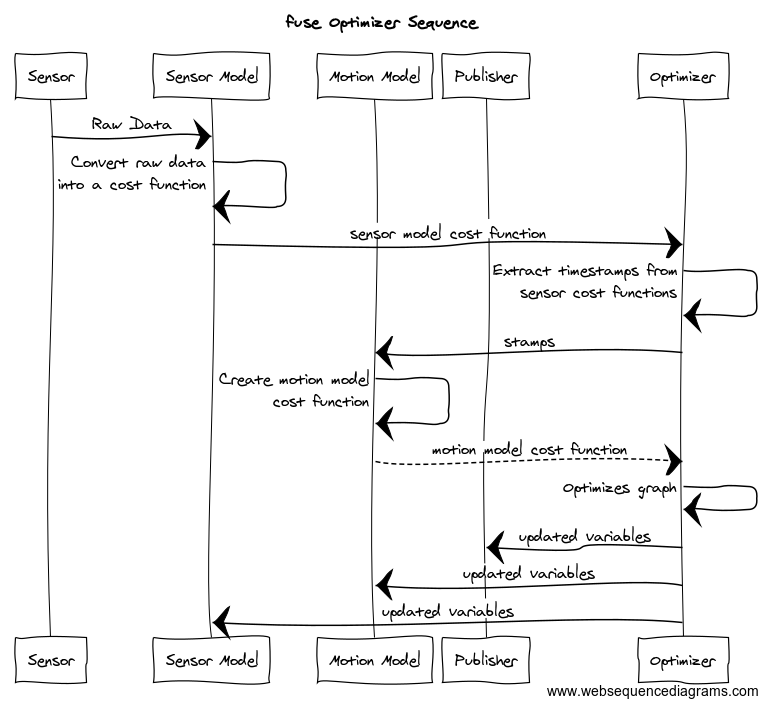
- A sensor model receives raw sensor data. The sensor model generates a constraint and sends it to the optimizer.
- The optimizer receives the new sensor constraint. A request is sent to each configured motion model to generate a constraint between the previous state and the new state involved in the sensor constraint.
- The motion model receives the request and generates the required constraints to connect the new state to the previously generated motion model chain. The motion model constraints are sent to the optimizer.
- The optimizer adds the new sensor model and motion model constraints and variables to the graph and computes the optimal values for each state variable.
- The optimal state values are sent to each configured publisher (as well as the sensor models and motion models).
- The publishers receive the optimized state values and publish any derived quantities on ROS topics.
- Repeat
It is important to note that much of this flow happens asynchronously in practice. Sensors are expected to operate independently from each other, so each sensor will be sending constraints to the optimizer at its own frequency. The optimizer will cache the constraints and process them in small batches on some schedule. The publishers may require considerable processing time, introducing a delay between the completion of the optimization cycle and the publishing of data to the ROS topic.

Example
Let’s consider a simple robotics example to illustrate this. Assume we have a typical indoor differential-drive robot. This robot has wheel encoders and a horizontal laser.
The first thing we must do is define our state variables. At a minimum, we want the robot pose at each timestamp.
We model the pose using a 2D position and an orientation. Each 2D pose at a specific time gets a unique variable
name. For ease of notation, let’s call the pose variables X1, X2, X3, etc. (In reality, each variable gets
a UUID, but those are much harder to write down.) Each 2D pose is instantiated as a example_robot::Pose2D which is
derived from the fuse_core::Variable base class. (fuse ships with several basic variables, such as 2D and 3D
versions of position, orientation, and velocity variables, but you can derive your own variable types as you need them.)
Next we need to decide how to model our sensors. We can model the wheel encoders as providing an incremental
pose measurement. Given a starting pose, X1, and a wheel encoder delta, z, we predict the pose X2' using some
measurement function f.
X2' = f(X1, z)
The error term for our constraint is the difference between the predicted pose X2' and the actual pose X2
error = X2'^-1 * X2
where X2'^-1 is the inverse of the pose X2'
We derive a fuse_core::Constraint that implements that error function. Similarly, we perform scan-to-scan matching
using out laser data and create an incremental pose constraint between consecutive scans.
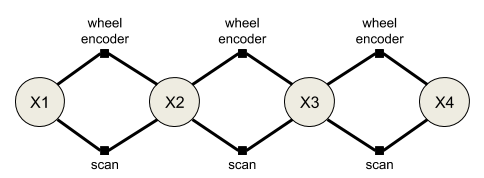
In the simplest example, the sensors are synchronized, i.e. the laser and the wheel encoders are sampled at the same
time. This is enough to construct our first fuse system. Below is the constraint graph generated from this first
system. The large circles represent state variables at a given time, while the small squares represent measurements.
The graph connectivity indicates which variables are involved in what measurements.
The two sensor models are configured as plugins to an optimizer implementation. The optimizer performs the required computation to generate the optimal state variable values based on the provided sensor constraints. We will never be able to exactly satisfy both the wheel encoder constraints and the laserscan constraints. Instead we minimize the error of all the constraints using nonlinear least squares optimization.

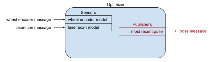
While our fuse system is optimizing constraints from two different sensors, it is not yet publishing any data back
out to ROS. In order to publish data to ROS, we derive a fuse_core::Publisher class and add it to the
optimizer. Derived publishers have access to the optimized values of all state variables. The specific publisher
implementation determines what type of messages are published and at what frequency. For our example system,
we would like visualize the current pose of the robot in RViz, so we create a fuse publisher that finds the most
recent pose and converts it into a geometry_msgs::msg::PoseStamped message, then publishes the message to a topic.
We finally have something that is starting to be useful.
Adaptation #1: Asynchronous sensors
Typically the laser measurements and the wheel encoder measurements are not synchronized. The encoder measurements are sampled faster than the laser, and are sampled at different times using a different clock. If we do not do anything different in this situation, the constraint graph becomes disconnected.
File truncated at 100 lines see the full file
CONTRIBUTING
|
|
fuse repositoryfuse fuse_constraints fuse_core fuse_doc fuse_graphs fuse_loss fuse_models fuse_msgs fuse_optimizers fuse_publishers fuse_tutorials fuse_variables fuse_viz |
ROS Distro
|
Repository Summary
| Checkout URI | https://github.com/locusrobotics/fuse.git |
| VCS Type | git |
| VCS Version | jazzy |
| Last Updated | 2025-08-29 |
| Dev Status | MAINTAINED |
| Released | RELEASED |
| Contributing |
Help Wanted (-)
Good First Issues (-) Pull Requests to Review (-) |
Packages
| Name | Version |
|---|---|
| fuse | 1.1.4 |
| fuse_constraints | 1.1.4 |
| fuse_core | 1.1.4 |
| fuse_doc | 1.1.4 |
| fuse_graphs | 1.1.4 |
| fuse_loss | 1.1.4 |
| fuse_models | 1.1.4 |
| fuse_msgs | 1.1.4 |
| fuse_optimizers | 1.1.4 |
| fuse_publishers | 1.1.4 |
| fuse_tutorials | 1.1.4 |
| fuse_variables | 1.1.4 |
| fuse_viz | 1.1.4 |
README
fuse
NOTE: The rolling branch is a work in progress port of the fuse stack to ROS 2, it is not expected to work until said work is done!
The fuse stack provides a general architecture for performing sensor fusion live on a robot. Some possible applications include state estimation, localization, mapping, and calibration.
Overview
fuse is a ROS framework for performing sensor fusion using nonlinear least squares optimization techniques. In particular, fuse provides:
- a plugin-based system for modeling sensor measurements
- a similar plugin-based system for motion models
- a plugin-based system for publishing optimized state values
- an extensible state variable definition
- a “contract” on how an optimizer will interact with the above components
- and some common implementations to get everyone started
(unpresented) ROSCon 2018 Lightning Talk slides
Data flows through the system approximately like this:
- A sensor model receives raw sensor data. The sensor model generates a constraint and sends it to the optimizer.
- The optimizer receives the new sensor constraint. A request is sent to each configured motion model to generate a constraint between the previous state and the new state involved in the sensor constraint.
- The motion model receives the request and generates the required constraints to connect the new state to the previously generated motion model chain. The motion model constraints are sent to the optimizer.
- The optimizer adds the new sensor model and motion model constraints and variables to the graph and computes the optimal values for each state variable.
- The optimal state values are sent to each configured publisher (as well as the sensor models and motion models).
- The publishers receive the optimized state values and publish any derived quantities on ROS topics.
- Repeat
It is important to note that much of this flow happens asynchronously in practice. Sensors are expected to operate independently from each other, so each sensor will be sending constraints to the optimizer at its own frequency. The optimizer will cache the constraints and process them in small batches on some schedule. The publishers may require considerable processing time, introducing a delay between the completion of the optimization cycle and the publishing of data to the ROS topic.
Example
Let’s consider a simple robotics example to illustrate this. Assume we have a typical indoor differential-drive robot. This robot has wheel encoders and a horizontal laser.
The first thing we must do is define our state variables. At a minimum, we want the robot pose at each timestamp.
We model the pose using a 2D position and an orientation. Each 2D pose at a specific time gets a unique variable
name. For ease of notation, let’s call the pose variables X1, X2, X3, etc. (In reality, each variable gets
a UUID, but those are much harder to write down.) Each 2D pose is instantiated as a example_robot::Pose2D which is
derived from the fuse_core::Variable base class. (fuse ships with several basic variables, such as 2D and 3D
versions of position, orientation, and velocity variables, but you can derive your own variable types as you need them.)
Next we need to decide how to model our sensors. We can model the wheel encoders as providing an incremental
pose measurement. Given a starting pose, X1, and a wheel encoder delta, z, we predict the pose X2' using some
measurement function f.
X2' = f(X1, z)
The error term for our constraint is the difference between the predicted pose X2' and the actual pose X2
error = X2'^-1 * X2
where X2'^-1 is the inverse of the pose X2'
We derive a fuse_core::Constraint that implements that error function. Similarly, we perform scan-to-scan matching
using out laser data and create an incremental pose constraint between consecutive scans.
In the simplest example, the sensors are synchronized, i.e. the laser and the wheel encoders are sampled at the same
time. This is enough to construct our first fuse system. Below is the constraint graph generated from this first
system. The large circles represent state variables at a given time, while the small squares represent measurements.
The graph connectivity indicates which variables are involved in what measurements.
The two sensor models are configured as plugins to an optimizer implementation. The optimizer performs the required computation to generate the optimal state variable values based on the provided sensor constraints. We will never be able to exactly satisfy both the wheel encoder constraints and the laserscan constraints. Instead we minimize the error of all the constraints using nonlinear least squares optimization.
While our fuse system is optimizing constraints from two different sensors, it is not yet publishing any data back
out to ROS. In order to publish data to ROS, we derive a fuse_core::Publisher class and add it to the
optimizer. Derived publishers have access to the optimized values of all state variables. The specific publisher
implementation determines what type of messages are published and at what frequency. For our example system,
we would like visualize the current pose of the robot in RViz, so we create a fuse publisher that finds the most
recent pose and converts it into a geometry_msgs::msg::PoseStamped message, then publishes the message to a topic.
We finally have something that is starting to be useful.
Adaptation #1: Asynchronous sensors
Typically the laser measurements and the wheel encoder measurements are not synchronized. The encoder measurements are sampled faster than the laser, and are sampled at different times using a different clock. If we do not do anything different in this situation, the constraint graph becomes disconnected.
File truncated at 100 lines see the full file
CONTRIBUTING
|
|
fuse repositoryfuse fuse_constraints fuse_core fuse_doc fuse_graphs fuse_loss fuse_models fuse_msgs fuse_optimizers fuse_publishers fuse_tutorials fuse_variables fuse_viz |
ROS Distro
|
Repository Summary
| Checkout URI | https://github.com/locusrobotics/fuse.git |
| VCS Type | git |
| VCS Version | rolling |
| Last Updated | 2025-08-29 |
| Dev Status | MAINTAINED |
| Released | RELEASED |
| Contributing |
Help Wanted (-)
Good First Issues (-) Pull Requests to Review (-) |
Packages
| Name | Version |
|---|---|
| fuse | 1.3.1 |
| fuse_constraints | 1.3.1 |
| fuse_core | 1.3.1 |
| fuse_doc | 1.3.1 |
| fuse_graphs | 1.3.1 |
| fuse_loss | 1.3.1 |
| fuse_models | 1.3.1 |
| fuse_msgs | 1.3.1 |
| fuse_optimizers | 1.3.1 |
| fuse_publishers | 1.3.1 |
| fuse_tutorials | 1.3.1 |
| fuse_variables | 1.3.1 |
| fuse_viz | 1.3.1 |
README
fuse
NOTE: The rolling branch is a work in progress port of the fuse stack to ROS 2, it is not expected to work until said work is done!
The fuse stack provides a general architecture for performing sensor fusion live on a robot. Some possible applications include state estimation, localization, mapping, and calibration.
Overview
fuse is a ROS framework for performing sensor fusion using nonlinear least squares optimization techniques. In particular, fuse provides:
- a plugin-based system for modeling sensor measurements
- a similar plugin-based system for motion models
- a plugin-based system for publishing optimized state values
- an extensible state variable definition
- a “contract” on how an optimizer will interact with the above components
- and some common implementations to get everyone started
(unpresented) ROSCon 2018 Lightning Talk slides
Data flows through the system approximately like this:
- A sensor model receives raw sensor data. The sensor model generates a constraint and sends it to the optimizer.
- The optimizer receives the new sensor constraint. A request is sent to each configured motion model to generate a constraint between the previous state and the new state involved in the sensor constraint.
- The motion model receives the request and generates the required constraints to connect the new state to the previously generated motion model chain. The motion model constraints are sent to the optimizer.
- The optimizer adds the new sensor model and motion model constraints and variables to the graph and computes the optimal values for each state variable.
- The optimal state values are sent to each configured publisher (as well as the sensor models and motion models).
- The publishers receive the optimized state values and publish any derived quantities on ROS topics.
- Repeat
It is important to note that much of this flow happens asynchronously in practice. Sensors are expected to operate independently from each other, so each sensor will be sending constraints to the optimizer at its own frequency. The optimizer will cache the constraints and process them in small batches on some schedule. The publishers may require considerable processing time, introducing a delay between the completion of the optimization cycle and the publishing of data to the ROS topic.
Example
Let’s consider a simple robotics example to illustrate this. Assume we have a typical indoor differential-drive robot. This robot has wheel encoders and a horizontal laser.
The first thing we must do is define our state variables. At a minimum, we want the robot pose at each timestamp.
We model the pose using a 2D position and an orientation. Each 2D pose at a specific time gets a unique variable
name. For ease of notation, let’s call the pose variables X1, X2, X3, etc. (In reality, each variable gets
a UUID, but those are much harder to write down.) Each 2D pose is instantiated as a example_robot::Pose2D which is
derived from the fuse_core::Variable base class. (fuse ships with several basic variables, such as 2D and 3D
versions of position, orientation, and velocity variables, but you can derive your own variable types as you need them.)
Next we need to decide how to model our sensors. We can model the wheel encoders as providing an incremental
pose measurement. Given a starting pose, X1, and a wheel encoder delta, z, we predict the pose X2' using some
measurement function f.
X2' = f(X1, z)
The error term for our constraint is the difference between the predicted pose X2' and the actual pose X2
error = X2'^-1 * X2
where X2'^-1 is the inverse of the pose X2'
We derive a fuse_core::Constraint that implements that error function. Similarly, we perform scan-to-scan matching
using out laser data and create an incremental pose constraint between consecutive scans.
In the simplest example, the sensors are synchronized, i.e. the laser and the wheel encoders are sampled at the same
time. This is enough to construct our first fuse system. Below is the constraint graph generated from this first
system. The large circles represent state variables at a given time, while the small squares represent measurements.
The graph connectivity indicates which variables are involved in what measurements.

The two sensor models are configured as plugins to an optimizer implementation. The optimizer performs the required computation to generate the optimal state variable values based on the provided sensor constraints. We will never be able to exactly satisfy both the wheel encoder constraints and the laserscan constraints. Instead we minimize the error of all the constraints using nonlinear least squares optimization.

While our fuse system is optimizing constraints from two different sensors, it is not yet publishing any data back
out to ROS. In order to publish data to ROS, we derive a fuse_core::Publisher class and add it to the
optimizer. Derived publishers have access to the optimized values of all state variables. The specific publisher
implementation determines what type of messages are published and at what frequency. For our example system,
we would like visualize the current pose of the robot in RViz, so we create a fuse publisher that finds the most
recent pose and converts it into a geometry_msgs::msg::PoseStamped message, then publishes the message to a topic.

We finally have something that is starting to be useful.
Adaptation #1: Asynchronous sensors
Typically the laser measurements and the wheel encoder measurements are not synchronized. The encoder measurements are sampled faster than the laser, and are sampled at different times using a different clock. If we do not do anything different in this situation, the constraint graph becomes disconnected.
File truncated at 100 lines see the full file
CONTRIBUTING
|
|
fuse repositoryfuse fuse_constraints fuse_core fuse_doc fuse_graphs fuse_loss fuse_models fuse_msgs fuse_optimizers fuse_publishers fuse_tutorials fuse_variables fuse_viz |
ROS Distro
|
Repository Summary
| Checkout URI | https://github.com/locusrobotics/fuse.git |
| VCS Type | git |
| VCS Version | rolling |
| Last Updated | 2025-08-29 |
| Dev Status | MAINTAINED |
| Released | RELEASED |
| Contributing |
Help Wanted (-)
Good First Issues (-) Pull Requests to Review (-) |
Packages
| Name | Version |
|---|---|
| fuse | 1.3.1 |
| fuse_constraints | 1.3.1 |
| fuse_core | 1.3.1 |
| fuse_doc | 1.3.1 |
| fuse_graphs | 1.3.1 |
| fuse_loss | 1.3.1 |
| fuse_models | 1.3.1 |
| fuse_msgs | 1.3.1 |
| fuse_optimizers | 1.3.1 |
| fuse_publishers | 1.3.1 |
| fuse_tutorials | 1.3.1 |
| fuse_variables | 1.3.1 |
| fuse_viz | 1.3.1 |
README
fuse
NOTE: The rolling branch is a work in progress port of the fuse stack to ROS 2, it is not expected to work until said work is done!
The fuse stack provides a general architecture for performing sensor fusion live on a robot. Some possible applications include state estimation, localization, mapping, and calibration.
Overview
fuse is a ROS framework for performing sensor fusion using nonlinear least squares optimization techniques. In particular, fuse provides:
- a plugin-based system for modeling sensor measurements
- a similar plugin-based system for motion models
- a plugin-based system for publishing optimized state values
- an extensible state variable definition
- a “contract” on how an optimizer will interact with the above components
- and some common implementations to get everyone started
(unpresented) ROSCon 2018 Lightning Talk slides
Data flows through the system approximately like this:
- A sensor model receives raw sensor data. The sensor model generates a constraint and sends it to the optimizer.
- The optimizer receives the new sensor constraint. A request is sent to each configured motion model to generate a constraint between the previous state and the new state involved in the sensor constraint.
- The motion model receives the request and generates the required constraints to connect the new state to the previously generated motion model chain. The motion model constraints are sent to the optimizer.
- The optimizer adds the new sensor model and motion model constraints and variables to the graph and computes the optimal values for each state variable.
- The optimal state values are sent to each configured publisher (as well as the sensor models and motion models).
- The publishers receive the optimized state values and publish any derived quantities on ROS topics.
- Repeat
It is important to note that much of this flow happens asynchronously in practice. Sensors are expected to operate independently from each other, so each sensor will be sending constraints to the optimizer at its own frequency. The optimizer will cache the constraints and process them in small batches on some schedule. The publishers may require considerable processing time, introducing a delay between the completion of the optimization cycle and the publishing of data to the ROS topic.
Example
Let’s consider a simple robotics example to illustrate this. Assume we have a typical indoor differential-drive robot. This robot has wheel encoders and a horizontal laser.
The first thing we must do is define our state variables. At a minimum, we want the robot pose at each timestamp.
We model the pose using a 2D position and an orientation. Each 2D pose at a specific time gets a unique variable
name. For ease of notation, let’s call the pose variables X1, X2, X3, etc. (In reality, each variable gets
a UUID, but those are much harder to write down.) Each 2D pose is instantiated as a example_robot::Pose2D which is
derived from the fuse_core::Variable base class. (fuse ships with several basic variables, such as 2D and 3D
versions of position, orientation, and velocity variables, but you can derive your own variable types as you need them.)
Next we need to decide how to model our sensors. We can model the wheel encoders as providing an incremental
pose measurement. Given a starting pose, X1, and a wheel encoder delta, z, we predict the pose X2' using some
measurement function f.
X2' = f(X1, z)
The error term for our constraint is the difference between the predicted pose X2' and the actual pose X2
error = X2'^-1 * X2
where X2'^-1 is the inverse of the pose X2'
We derive a fuse_core::Constraint that implements that error function. Similarly, we perform scan-to-scan matching
using out laser data and create an incremental pose constraint between consecutive scans.
In the simplest example, the sensors are synchronized, i.e. the laser and the wheel encoders are sampled at the same
time. This is enough to construct our first fuse system. Below is the constraint graph generated from this first
system. The large circles represent state variables at a given time, while the small squares represent measurements.
The graph connectivity indicates which variables are involved in what measurements.
The two sensor models are configured as plugins to an optimizer implementation. The optimizer performs the required computation to generate the optimal state variable values based on the provided sensor constraints. We will never be able to exactly satisfy both the wheel encoder constraints and the laserscan constraints. Instead we minimize the error of all the constraints using nonlinear least squares optimization.
While our fuse system is optimizing constraints from two different sensors, it is not yet publishing any data back
out to ROS. In order to publish data to ROS, we derive a fuse_core::Publisher class and add it to the
optimizer. Derived publishers have access to the optimized values of all state variables. The specific publisher
implementation determines what type of messages are published and at what frequency. For our example system,
we would like visualize the current pose of the robot in RViz, so we create a fuse publisher that finds the most
recent pose and converts it into a geometry_msgs::msg::PoseStamped message, then publishes the message to a topic.
We finally have something that is starting to be useful.
Adaptation #1: Asynchronous sensors
Typically the laser measurements and the wheel encoder measurements are not synchronized. The encoder measurements are sampled faster than the laser, and are sampled at different times using a different clock. If we do not do anything different in this situation, the constraint graph becomes disconnected.
File truncated at 100 lines see the full file
CONTRIBUTING
|
|
fuse repositoryfuse fuse_constraints fuse_core fuse_doc fuse_graphs fuse_loss fuse_models fuse_msgs fuse_optimizers fuse_publishers fuse_tutorials fuse_variables fuse_viz |
ROS Distro
|
Repository Summary
| Checkout URI | https://github.com/locusrobotics/fuse.git |
| VCS Type | git |
| VCS Version | jazzy |
| Last Updated | 2025-08-29 |
| Dev Status | MAINTAINED |
| Released | RELEASED |
| Contributing |
Help Wanted (-)
Good First Issues (-) Pull Requests to Review (-) |
Packages
| Name | Version |
|---|---|
| fuse | 1.1.4 |
| fuse_constraints | 1.1.4 |
| fuse_core | 1.1.4 |
| fuse_doc | 1.1.4 |
| fuse_graphs | 1.1.4 |
| fuse_loss | 1.1.4 |
| fuse_models | 1.1.4 |
| fuse_msgs | 1.1.4 |
| fuse_optimizers | 1.1.4 |
| fuse_publishers | 1.1.4 |
| fuse_tutorials | 1.1.4 |
| fuse_variables | 1.1.4 |
| fuse_viz | 1.1.4 |
README
fuse
NOTE: The rolling branch is a work in progress port of the fuse stack to ROS 2, it is not expected to work until said work is done!
The fuse stack provides a general architecture for performing sensor fusion live on a robot. Some possible applications include state estimation, localization, mapping, and calibration.
Overview
fuse is a ROS framework for performing sensor fusion using nonlinear least squares optimization techniques. In particular, fuse provides:
- a plugin-based system for modeling sensor measurements
- a similar plugin-based system for motion models
- a plugin-based system for publishing optimized state values
- an extensible state variable definition
- a “contract” on how an optimizer will interact with the above components
- and some common implementations to get everyone started
(unpresented) ROSCon 2018 Lightning Talk slides
Data flows through the system approximately like this:
- A sensor model receives raw sensor data. The sensor model generates a constraint and sends it to the optimizer.
- The optimizer receives the new sensor constraint. A request is sent to each configured motion model to generate a constraint between the previous state and the new state involved in the sensor constraint.
- The motion model receives the request and generates the required constraints to connect the new state to the previously generated motion model chain. The motion model constraints are sent to the optimizer.
- The optimizer adds the new sensor model and motion model constraints and variables to the graph and computes the optimal values for each state variable.
- The optimal state values are sent to each configured publisher (as well as the sensor models and motion models).
- The publishers receive the optimized state values and publish any derived quantities on ROS topics.
- Repeat
It is important to note that much of this flow happens asynchronously in practice. Sensors are expected to operate independently from each other, so each sensor will be sending constraints to the optimizer at its own frequency. The optimizer will cache the constraints and process them in small batches on some schedule. The publishers may require considerable processing time, introducing a delay between the completion of the optimization cycle and the publishing of data to the ROS topic.
Example
Let’s consider a simple robotics example to illustrate this. Assume we have a typical indoor differential-drive robot. This robot has wheel encoders and a horizontal laser.
The first thing we must do is define our state variables. At a minimum, we want the robot pose at each timestamp.
We model the pose using a 2D position and an orientation. Each 2D pose at a specific time gets a unique variable
name. For ease of notation, let’s call the pose variables X1, X2, X3, etc. (In reality, each variable gets
a UUID, but those are much harder to write down.) Each 2D pose is instantiated as a example_robot::Pose2D which is
derived from the fuse_core::Variable base class. (fuse ships with several basic variables, such as 2D and 3D
versions of position, orientation, and velocity variables, but you can derive your own variable types as you need them.)
Next we need to decide how to model our sensors. We can model the wheel encoders as providing an incremental
pose measurement. Given a starting pose, X1, and a wheel encoder delta, z, we predict the pose X2' using some
measurement function f.
X2' = f(X1, z)
The error term for our constraint is the difference between the predicted pose X2' and the actual pose X2
error = X2'^-1 * X2
where X2'^-1 is the inverse of the pose X2'
We derive a fuse_core::Constraint that implements that error function. Similarly, we perform scan-to-scan matching
using out laser data and create an incremental pose constraint between consecutive scans.
In the simplest example, the sensors are synchronized, i.e. the laser and the wheel encoders are sampled at the same
time. This is enough to construct our first fuse system. Below is the constraint graph generated from this first
system. The large circles represent state variables at a given time, while the small squares represent measurements.
The graph connectivity indicates which variables are involved in what measurements.
The two sensor models are configured as plugins to an optimizer implementation. The optimizer performs the required computation to generate the optimal state variable values based on the provided sensor constraints. We will never be able to exactly satisfy both the wheel encoder constraints and the laserscan constraints. Instead we minimize the error of all the constraints using nonlinear least squares optimization.
While our fuse system is optimizing constraints from two different sensors, it is not yet publishing any data back
out to ROS. In order to publish data to ROS, we derive a fuse_core::Publisher class and add it to the
optimizer. Derived publishers have access to the optimized values of all state variables. The specific publisher
implementation determines what type of messages are published and at what frequency. For our example system,
we would like visualize the current pose of the robot in RViz, so we create a fuse publisher that finds the most
recent pose and converts it into a geometry_msgs::msg::PoseStamped message, then publishes the message to a topic.
We finally have something that is starting to be useful.
Adaptation #1: Asynchronous sensors
Typically the laser measurements and the wheel encoder measurements are not synchronized. The encoder measurements are sampled faster than the laser, and are sampled at different times using a different clock. If we do not do anything different in this situation, the constraint graph becomes disconnected.
File truncated at 100 lines see the full file
CONTRIBUTING
|
|
fuse repositoryfuse fuse_constraints fuse_core fuse_doc fuse_graphs fuse_loss fuse_models fuse_msgs fuse_optimizers fuse_publishers fuse_tutorials fuse_variables fuse_viz |
ROS Distro
|
Repository Summary
| Checkout URI | https://github.com/locusrobotics/fuse.git |
| VCS Type | git |
| VCS Version | iron |
| Last Updated | 2024-10-31 |
| Dev Status | MAINTAINED |
| Released | RELEASED |
| Contributing |
Help Wanted (-)
Good First Issues (-) Pull Requests to Review (-) |
Packages
| Name | Version |
|---|---|
| fuse | 1.0.1 |
| fuse_constraints | 1.0.1 |
| fuse_core | 1.0.1 |
| fuse_doc | 1.0.1 |
| fuse_graphs | 1.0.1 |
| fuse_loss | 1.0.1 |
| fuse_models | 1.0.1 |
| fuse_msgs | 1.0.1 |
| fuse_optimizers | 1.0.1 |
| fuse_publishers | 1.0.1 |
| fuse_tutorials | 1.0.1 |
| fuse_variables | 1.0.1 |
| fuse_viz | 1.0.1 |
README
fuse
NOTE: The rolling branch is a work in progress port of the fuse stack to ROS 2, it is not expected to work until said work is done!
The fuse stack provides a general architecture for performing sensor fusion live on a robot. Some possible applications include state estimation, localization, mapping, and calibration.
Overview
fuse is a ROS framework for performing sensor fusion using nonlinear least squares optimization techniques. In particular, fuse provides:
- a plugin-based system for modeling sensor measurements
- a similar plugin-based system for motion models
- a plugin-based system for publishing optimized state values
- an extensible state variable definition
- a “contract” on how an optimizer will interact with the above components
- and some common implementations to get everyone started
(unpresented) ROSCon 2018 Lightning Talk slides
Data flows through the system approximately like this:
- A sensor model receives raw sensor data. The sensor model generates a constraint and sends it to the optimizer.
- The optimizer receives the new sensor constraint. A request is sent to each configured motion model to generate a constraint between the previous state and the new state involved in the sensor constraint.
- The motion model receives the request and generates the required constraints to connect the new state to the previously generated motion model chain. The motion model constraints are sent to the optimizer.
- The optimizer adds the new sensor model and motion model constraints and variables to the graph and computes the optimal values for each state variable.
- The optimal state values are sent to each configured publisher (as well as the sensor models and motion models).
- The publishers receive the optimized state values and publish any derived quantities on ROS topics.
- Repeat
It is important to note that much of this flow happens asynchronously in practice. Sensors are expected to operate independently from each other, so each sensor will be sending constraints to the optimizer at its own frequency. The optimizer will cache the constraints and process them in small batches on some schedule. The publishers may require considerable processing time, introducing a delay between the completion of the optimization cycle and the publishing of data to the ROS topic.

Example
Let’s consider a simple robotics example to illustrate this. Assume we have a typical indoor differential-drive robot. This robot has wheel encoders and a horizontal laser.
The first thing we must do is define our state variables. At a minimum, we want the robot pose at each timestamp.
We model the pose using a 2D position and an orientation. Each 2D pose at a specific time gets a unique variable
name. For ease of notation, let’s call the pose variables X1, X2, X3, etc. (In reality, each variable gets
a UUID, but those are much harder to write down.) Each 2D pose is instantiated as a example_robot::Pose2D which is
derived from the fuse_core::Variable base class. (fuse ships with several basic variables, such as 2D and 3D
versions of position, orientation, and velocity variables, but you can derive your own variable types as you need them.)
Next we need to decide how to model our sensors. We can model the wheel encoders as providing an incremental
pose measurement. Given a starting pose, X1, and a wheel encoder delta, z, we predict the pose X2' using some
measurement function f.
X2' = f(X1, z)
The error term for our constraint is the difference between the predicted pose X2' and the actual pose X2
error = X2'^-1 * X2
where X2'^-1 is the inverse of the pose X2'
We derive a fuse_core::Constraint that implements that error function. Similarly, we perform scan-to-scan matching
using out laser data and create an incremental pose constraint between consecutive scans.
In the simplest example, the sensors are synchronized, i.e. the laser and the wheel encoders are sampled at the same
time. This is enough to construct our first fuse system. Below is the constraint graph generated from this first
system. The large circles represent state variables at a given time, while the small squares represent measurements.
The graph connectivity indicates which variables are involved in what measurements.

The two sensor models are configured as plugins to an optimizer implementation. The optimizer performs the required computation to generate the optimal state variable values based on the provided sensor constraints. We will never be able to exactly satisfy both the wheel encoder constraints and the laserscan constraints. Instead we minimize the error of all the constraints using nonlinear least squares optimization.

While our fuse system is optimizing constraints from two different sensors, it is not yet publishing any data back
out to ROS. In order to publish data to ROS, we derive a fuse_core::Publisher class and add it to the
optimizer. Derived publishers have access to the optimized values of all state variables. The specific publisher
implementation determines what type of messages are published and at what frequency. For our example system,
we would like visualize the current pose of the robot in RViz, so we create a fuse publisher that finds the most
recent pose and converts it into a geometry_msgs::msg::PoseStamped message, then publishes the message to a topic.

We finally have something that is starting to be useful.
Adaptation #1: Asynchronous sensors
Typically the laser measurements and the wheel encoder measurements are not synchronized. The encoder measurements are sampled faster than the laser, and are sampled at different times using a different clock. If we do not do anything different in this situation, the constraint graph becomes disconnected.
File truncated at 100 lines see the full file
CONTRIBUTING
|
|
fuse repositoryfuse fuse_constraints fuse_core fuse_doc fuse_graphs fuse_loss fuse_models fuse_msgs fuse_optimizers fuse_publishers fuse_tutorials fuse_variables fuse_viz |
ROS Distro
|
Repository Summary
| Checkout URI | https://github.com/locusrobotics/fuse.git |
| VCS Type | git |
| VCS Version | jazzy |
| Last Updated | 2025-08-29 |
| Dev Status | MAINTAINED |
| Released | RELEASED |
| Contributing |
Help Wanted (-)
Good First Issues (-) Pull Requests to Review (-) |
Packages
| Name | Version |
|---|---|
| fuse | 1.1.4 |
| fuse_constraints | 1.1.4 |
| fuse_core | 1.1.4 |
| fuse_doc | 1.1.4 |
| fuse_graphs | 1.1.4 |
| fuse_loss | 1.1.4 |
| fuse_models | 1.1.4 |
| fuse_msgs | 1.1.4 |
| fuse_optimizers | 1.1.4 |
| fuse_publishers | 1.1.4 |
| fuse_tutorials | 1.1.4 |
| fuse_variables | 1.1.4 |
| fuse_viz | 1.1.4 |
README
fuse
NOTE: The rolling branch is a work in progress port of the fuse stack to ROS 2, it is not expected to work until said work is done!
The fuse stack provides a general architecture for performing sensor fusion live on a robot. Some possible applications include state estimation, localization, mapping, and calibration.
Overview
fuse is a ROS framework for performing sensor fusion using nonlinear least squares optimization techniques. In particular, fuse provides:
- a plugin-based system for modeling sensor measurements
- a similar plugin-based system for motion models
- a plugin-based system for publishing optimized state values
- an extensible state variable definition
- a “contract” on how an optimizer will interact with the above components
- and some common implementations to get everyone started
(unpresented) ROSCon 2018 Lightning Talk slides
Data flows through the system approximately like this:
- A sensor model receives raw sensor data. The sensor model generates a constraint and sends it to the optimizer.
- The optimizer receives the new sensor constraint. A request is sent to each configured motion model to generate a constraint between the previous state and the new state involved in the sensor constraint.
- The motion model receives the request and generates the required constraints to connect the new state to the previously generated motion model chain. The motion model constraints are sent to the optimizer.
- The optimizer adds the new sensor model and motion model constraints and variables to the graph and computes the optimal values for each state variable.
- The optimal state values are sent to each configured publisher (as well as the sensor models and motion models).
- The publishers receive the optimized state values and publish any derived quantities on ROS topics.
- Repeat
It is important to note that much of this flow happens asynchronously in practice. Sensors are expected to operate independently from each other, so each sensor will be sending constraints to the optimizer at its own frequency. The optimizer will cache the constraints and process them in small batches on some schedule. The publishers may require considerable processing time, introducing a delay between the completion of the optimization cycle and the publishing of data to the ROS topic.
Example
Let’s consider a simple robotics example to illustrate this. Assume we have a typical indoor differential-drive robot. This robot has wheel encoders and a horizontal laser.
The first thing we must do is define our state variables. At a minimum, we want the robot pose at each timestamp.
We model the pose using a 2D position and an orientation. Each 2D pose at a specific time gets a unique variable
name. For ease of notation, let’s call the pose variables X1, X2, X3, etc. (In reality, each variable gets
a UUID, but those are much harder to write down.) Each 2D pose is instantiated as a example_robot::Pose2D which is
derived from the fuse_core::Variable base class. (fuse ships with several basic variables, such as 2D and 3D
versions of position, orientation, and velocity variables, but you can derive your own variable types as you need them.)
Next we need to decide how to model our sensors. We can model the wheel encoders as providing an incremental
pose measurement. Given a starting pose, X1, and a wheel encoder delta, z, we predict the pose X2' using some
measurement function f.
X2' = f(X1, z)
The error term for our constraint is the difference between the predicted pose X2' and the actual pose X2
error = X2'^-1 * X2
where X2'^-1 is the inverse of the pose X2'
We derive a fuse_core::Constraint that implements that error function. Similarly, we perform scan-to-scan matching
using out laser data and create an incremental pose constraint between consecutive scans.
In the simplest example, the sensors are synchronized, i.e. the laser and the wheel encoders are sampled at the same
time. This is enough to construct our first fuse system. Below is the constraint graph generated from this first
system. The large circles represent state variables at a given time, while the small squares represent measurements.
The graph connectivity indicates which variables are involved in what measurements.
The two sensor models are configured as plugins to an optimizer implementation. The optimizer performs the required computation to generate the optimal state variable values based on the provided sensor constraints. We will never be able to exactly satisfy both the wheel encoder constraints and the laserscan constraints. Instead we minimize the error of all the constraints using nonlinear least squares optimization.
While our fuse system is optimizing constraints from two different sensors, it is not yet publishing any data back
out to ROS. In order to publish data to ROS, we derive a fuse_core::Publisher class and add it to the
optimizer. Derived publishers have access to the optimized values of all state variables. The specific publisher
implementation determines what type of messages are published and at what frequency. For our example system,
we would like visualize the current pose of the robot in RViz, so we create a fuse publisher that finds the most
recent pose and converts it into a geometry_msgs::msg::PoseStamped message, then publishes the message to a topic.
We finally have something that is starting to be useful.
Adaptation #1: Asynchronous sensors
Typically the laser measurements and the wheel encoder measurements are not synchronized. The encoder measurements are sampled faster than the laser, and are sampled at different times using a different clock. If we do not do anything different in this situation, the constraint graph becomes disconnected.
File truncated at 100 lines see the full file
CONTRIBUTING
|
|
fuse repositoryfuse fuse_constraints fuse_core fuse_doc fuse_graphs fuse_loss fuse_models fuse_msgs fuse_optimizers fuse_publishers fuse_tutorials fuse_variables fuse_viz |
ROS Distro
|
Repository Summary
| Checkout URI | https://github.com/locusrobotics/fuse.git |
| VCS Type | git |
| VCS Version | devel |
| Last Updated | 2026-03-06 |
| Dev Status | MAINTAINED |
| Released | RELEASED |
| Contributing |
Help Wanted (-)
Good First Issues (-) Pull Requests to Review (-) |
Packages
| Name | Version |
|---|---|
| fuse | 0.14.0 |
| fuse_constraints | 0.14.0 |
| fuse_core | 0.14.0 |
| fuse_doc | 0.14.0 |
| fuse_graphs | 0.14.0 |
| fuse_loss | 0.14.0 |
| fuse_models | 0.14.0 |
| fuse_msgs | 0.14.0 |
| fuse_optimizers | 0.14.0 |
| fuse_publishers | 0.14.0 |
| fuse_tutorials | 0.14.0 |
| fuse_variables | 0.14.0 |
| fuse_viz | 0.14.0 |
README
fuse
The fuse stack provides a general architecture for performing sensor fusion live on a robot. Some possible applications include state estimation, localization, mapping, and calibration.
Overview
fuse is a ROS framework for performing sensor fusion using nonlinear least squares optimization techniques. In particular, fuse provides:
- a plugin-based system for modeling sensor measurements
- a similar plugin-based system for motion models
- a plugin-based system for publishing optimized state values
- an extensible state variable definition
- a “contract” on how an optimizer will interact with the above components
- and some common implementations to get everyone started
(unpresented) ROSCon 2018 Lightning Talk slides
Data flows through the system approximately like this:
- A sensor model receives raw sensor data. The sensor model generates a constraint and sends it to the optimizer.
- The optimizer receives the new sensor constraint. A request is sent to each configured motion model to generate a constraint between the previous state and the new state involved in the sensor constraint.
- The motion model receives the request and generates the required constraints to connect the new state to the previously generated motion model chain. The motion model constraints are sent to the optimizer.
- The optimizer adds the new sensor model and motion model constraints and variables to the graph and computes the optimal values for each state variable.
- The optimal state values are sent to each configured publisher (as well as the sensor models and motion models).
- The publishers receive the optimized state values and publish any derived quantities on ROS topics.
- Repeat
It is important to note that much of this flow happens asynchronously in practice. Sensors are expected to operate independently from each other, so each sensor will be sending constraints to the optimizer at its own frequency. The optimizer will cache the constraints and process them in small batches on some schedule. The publishers may require considerable processing time, introducing a delay between the completion of the optimization cycle and the publishing of data to the ROS topic.

Example
Let’s consider a simple robotics example to illustrate this. Assume we have a typical indoor differential-drive robot. This robot has wheel encoders and a horizontal laser.
The first thing we must do is define our state variables. At a minimum, we want the robot pose at each timestamp.
We model the pose using a 2D position and an orientation. Each 2D pose at a specific time gets a unique variable
name. For ease of notation, let’s call the pose variables X1, X2, X3, etc. (In reality, each variable gets
a UUID, but those are much harder to write down.) Each 2D pose is instantiated as a example_robot::Pose2D which is
derived from the fuse_core::Variable base class. (fuse ships with several basic variables, such as 2D and 3D
versions of position, orientation, and velocity variables, but you can derive your own variable types as you need them.)
Next we need to decide how to model our sensors. We can model the wheel encoders as providing an incremental
pose measurement. Given a starting pose, X1, and a wheel encoder delta, z, we predict the pose X2' using some
measurement function f.
X2' = f(X1, z)
The error term for our constraint is the difference between the predicted pose X2' and the actual pose X2
error = X2'^-1 * X2
where X2'^-1 is the inverse of the pose X2'
We derive a fuse_core::Constraint that implements that error function. Similarly, we perform scan-to-scan matching
using out laser data and create an incremental pose constraint between consecutive scans.
In the simplest example, the sensors are synchronized, i.e. the laser and the wheel encoders are sampled at the same
time. This is enough to construct our first fuse system. Below is the constraint graph generated from this first
system. The large circles represent state variables at a given time, while the small squares represent measurements.
The graph connectivity indicates which variables are involved in what measurements.

The two sensor models are configured as plugins to an optimizer implementation. The optimizer performs the required computation to generate the optimal state variable values based on the provided sensor constraints. We will never be able to exactly satisfy both the wheel encoder constraints and the laserscan constraints. Instead we minimize the error of all the constraints using nonlinear least squares optimization.

While our fuse system is optimizing constraints from two different sensors, it is not yet publishing any data back
out to ROS. In order to publish data to ROS, we derive a fuse_core::Publisher class and add it to the
optimizer. Derived publishers have access to the optimized values of all state variables. The specific publisher
implementation determines what type of messages are published and at what frequency. For our example system,
we would like visualize the current pose of the robot in RViz, so we create a fuse publisher that finds the most
recent pose and converts it into a geometry_msgs::PoseStamped message, then publishes the message to a topic.

We finally have something that is starting to be useful.
Adaptation #1: Asynchronous sensors
Typically the laser measurements and the wheel encoder measurements are not synchronized. The encoder measurements are sampled faster than the laser, and are sampled at different times using a different clock. If we do not do anything different in this situation, the constraint graph becomes disconnected.
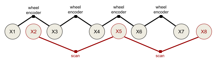
File truncated at 100 lines see the full file
CONTRIBUTING
|
|
fuse repositoryfuse fuse_constraints fuse_core fuse_doc fuse_graphs fuse_loss fuse_models fuse_msgs fuse_optimizers fuse_publishers fuse_tutorials fuse_variables fuse_viz |
ROS Distro
|
Repository Summary
| Checkout URI | https://github.com/locusrobotics/fuse.git |
| VCS Type | git |
| VCS Version | devel |
| Last Updated | 2026-03-06 |
| Dev Status | MAINTAINED |
| Released | RELEASED |
| Contributing |
Help Wanted (-)
Good First Issues (-) Pull Requests to Review (-) |
Packages
| Name | Version |
|---|---|
| fuse | 0.14.0 |
| fuse_constraints | 0.14.0 |
| fuse_core | 0.14.0 |
| fuse_doc | 0.14.0 |
| fuse_graphs | 0.14.0 |
| fuse_loss | 0.14.0 |
| fuse_models | 0.14.0 |
| fuse_msgs | 0.14.0 |
| fuse_optimizers | 0.14.0 |
| fuse_publishers | 0.14.0 |
| fuse_tutorials | 0.14.0 |
| fuse_variables | 0.14.0 |
| fuse_viz | 0.14.0 |
README
fuse
The fuse stack provides a general architecture for performing sensor fusion live on a robot. Some possible applications include state estimation, localization, mapping, and calibration.
Overview
fuse is a ROS framework for performing sensor fusion using nonlinear least squares optimization techniques. In particular, fuse provides:
- a plugin-based system for modeling sensor measurements
- a similar plugin-based system for motion models
- a plugin-based system for publishing optimized state values
- an extensible state variable definition
- a “contract” on how an optimizer will interact with the above components
- and some common implementations to get everyone started
(unpresented) ROSCon 2018 Lightning Talk slides
Data flows through the system approximately like this:
- A sensor model receives raw sensor data. The sensor model generates a constraint and sends it to the optimizer.
- The optimizer receives the new sensor constraint. A request is sent to each configured motion model to generate a constraint between the previous state and the new state involved in the sensor constraint.
- The motion model receives the request and generates the required constraints to connect the new state to the previously generated motion model chain. The motion model constraints are sent to the optimizer.
- The optimizer adds the new sensor model and motion model constraints and variables to the graph and computes the optimal values for each state variable.
- The optimal state values are sent to each configured publisher (as well as the sensor models and motion models).
- The publishers receive the optimized state values and publish any derived quantities on ROS topics.
- Repeat
It is important to note that much of this flow happens asynchronously in practice. Sensors are expected to operate independently from each other, so each sensor will be sending constraints to the optimizer at its own frequency. The optimizer will cache the constraints and process them in small batches on some schedule. The publishers may require considerable processing time, introducing a delay between the completion of the optimization cycle and the publishing of data to the ROS topic.
Example
Let’s consider a simple robotics example to illustrate this. Assume we have a typical indoor differential-drive robot. This robot has wheel encoders and a horizontal laser.
The first thing we must do is define our state variables. At a minimum, we want the robot pose at each timestamp.
We model the pose using a 2D position and an orientation. Each 2D pose at a specific time gets a unique variable
name. For ease of notation, let’s call the pose variables X1, X2, X3, etc. (In reality, each variable gets
a UUID, but those are much harder to write down.) Each 2D pose is instantiated as a example_robot::Pose2D which is
derived from the fuse_core::Variable base class. (fuse ships with several basic variables, such as 2D and 3D
versions of position, orientation, and velocity variables, but you can derive your own variable types as you need them.)
Next we need to decide how to model our sensors. We can model the wheel encoders as providing an incremental
pose measurement. Given a starting pose, X1, and a wheel encoder delta, z, we predict the pose X2' using some
measurement function f.
X2' = f(X1, z)
The error term for our constraint is the difference between the predicted pose X2' and the actual pose X2
error = X2'^-1 * X2
where X2'^-1 is the inverse of the pose X2'
We derive a fuse_core::Constraint that implements that error function. Similarly, we perform scan-to-scan matching
using out laser data and create an incremental pose constraint between consecutive scans.
In the simplest example, the sensors are synchronized, i.e. the laser and the wheel encoders are sampled at the same
time. This is enough to construct our first fuse system. Below is the constraint graph generated from this first
system. The large circles represent state variables at a given time, while the small squares represent measurements.
The graph connectivity indicates which variables are involved in what measurements.
The two sensor models are configured as plugins to an optimizer implementation. The optimizer performs the required computation to generate the optimal state variable values based on the provided sensor constraints. We will never be able to exactly satisfy both the wheel encoder constraints and the laserscan constraints. Instead we minimize the error of all the constraints using nonlinear least squares optimization.
While our fuse system is optimizing constraints from two different sensors, it is not yet publishing any data back
out to ROS. In order to publish data to ROS, we derive a fuse_core::Publisher class and add it to the
optimizer. Derived publishers have access to the optimized values of all state variables. The specific publisher
implementation determines what type of messages are published and at what frequency. For our example system,
we would like visualize the current pose of the robot in RViz, so we create a fuse publisher that finds the most
recent pose and converts it into a geometry_msgs::PoseStamped message, then publishes the message to a topic.
We finally have something that is starting to be useful.
Adaptation #1: Asynchronous sensors
Typically the laser measurements and the wheel encoder measurements are not synchronized. The encoder measurements are sampled faster than the laser, and are sampled at different times using a different clock. If we do not do anything different in this situation, the constraint graph becomes disconnected.
File truncated at 100 lines see the full file