
|
andino_hardware package from andino repoandino_apps andino_base andino_bringup andino_control andino_description andino_firmware andino_gz_classic andino_hardware andino_navigation andino_slam |
ROS Distro
|
Package Summary
| Version | 0.2.0 |
| License | BSD Clause 3 |
| Build type | AMENT_CMAKE |
| Use | RECOMMENDED |
Repository Summary
| Checkout URI | https://github.com/Ekumen-OS/andino.git |
| VCS Type | git |
| VCS Version | humble |
| Last Updated | 2026-02-20 |
| Dev Status | DEVELOPED |
| Released | RELEASED |
| Contributing |
Help Wanted (-)
Good First Issues (-) Pull Requests to Review (-) |
Package Description
Maintainers
- Franco Cipollone
- Javier Balloffet
Authors
andino_hardware
This package aims to provide the necessary information to the correct assembly of the robot.
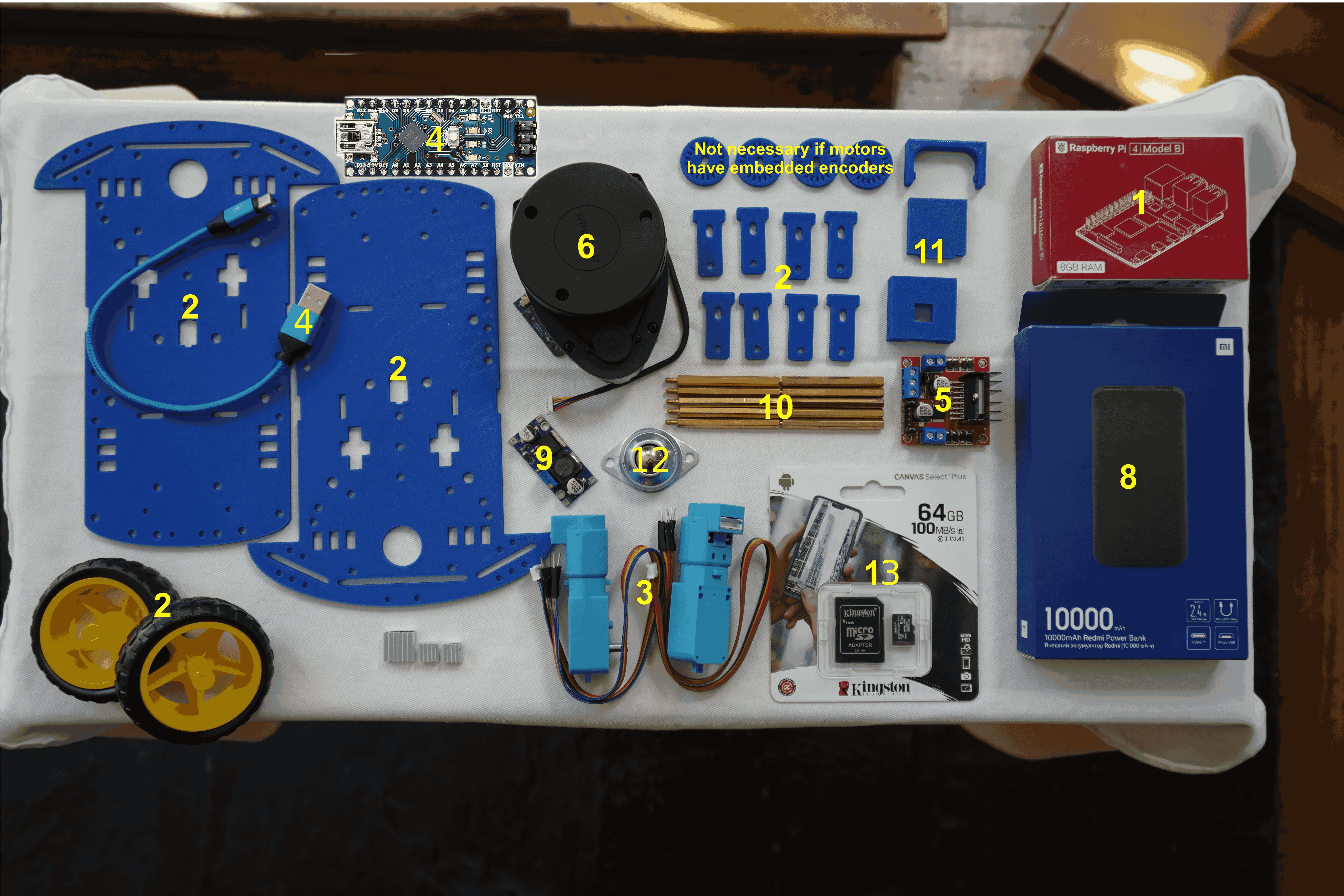
Bill of Materials
| Number | Module | Part | Links | Comments |
|---|---|---|---|---|
| 1 | SBC | Raspberry Pi 4 B (4 Gb) | PiShop, TiendaTec | If you want better performance you could buy the 8GB model |
| 2 | Chassis | 2 x Print 3d Chassis + Rubber Tyre Wheels | Chassis, Wheels Sparkfun | - |
| 3 | Motors | 2 x Motor with Encoder | Sparkfun | - |
| 4 | Microcontroller | Arduino Nano | Amazon | You can also use an Arduino Uno, but mind size. It should include a microUSB - USB cable. If not, you will need to purchase it. |
| 5 | Motor Driver | L298N Dual H Bridge | Amazon | - |
| 6 | Laser Scanner | RPLidar A1M8 | RobotShop, Amazon | If no microUSB-USB cable is included, you will need to purchase one |
| 7 | Camera | Raspi Camera Module V2, 8 MP | Robotshop, Amazon, Longer cable | A link for a longer cable (30 cm) is included, just in case the one included with the camera is too short. |
| 8 | Electrical Power Supply | Powerbank 5V | Amazon | Any powerbank is suitable: Mind size / weight / output current(>=2A) |
| 9 | Power Step up | DC - DC boost converter | Amazon Europe | If motors support higher voltage than 5V a step-up(e.g: to 9V) can be added between powerbank (5V) and motor driver. Screw clockwise to reduce the output voltage. |
| 10 | Fixing & Mount | M3 bolts/fasteners - M3 Spacers - M2.5/2.0 bolts/fasteners for SBC | Mercado Libre, Amazon, Spacers | You will probably need to replace the default spacers for the LiDAR with M3 spacers |
| 11 | Other 3D printed parts | Camera Mount | 3D models | These parts are for fixing the Raspi Cam at the front of the robot |
| 12 | Caster wheel | Caster wheel | Amazon | - |
| 13 | SD Card | 64 GB SD Card | Apokin, Amazon | The SD Card is used to host the OS for the Raspberry Pi |
| 14 | (Optional) Plastic seals | - | - | You will need at least 2 longer ones to fix the powerbank to the upper chassis, and the shorter ones for all the wires. If you don’t want to use them, you can use other method to fix the powerbank and wires |
When you gather all the parts, you should have the following (NOTE: the printed encoder wheels are no longer necessary, since the motors are equipped with an embedded encoder):
Tooling
| Number | Tool | Links | Comments |
|---|---|---|---|
| 1 | Set of screwdrivers | Amazon | You need flat and star screwdrivers |
| 2 | Silicon Pistol | Amazon | This pistol should include 75 silicon bars so you won’t need to purchase them separately |
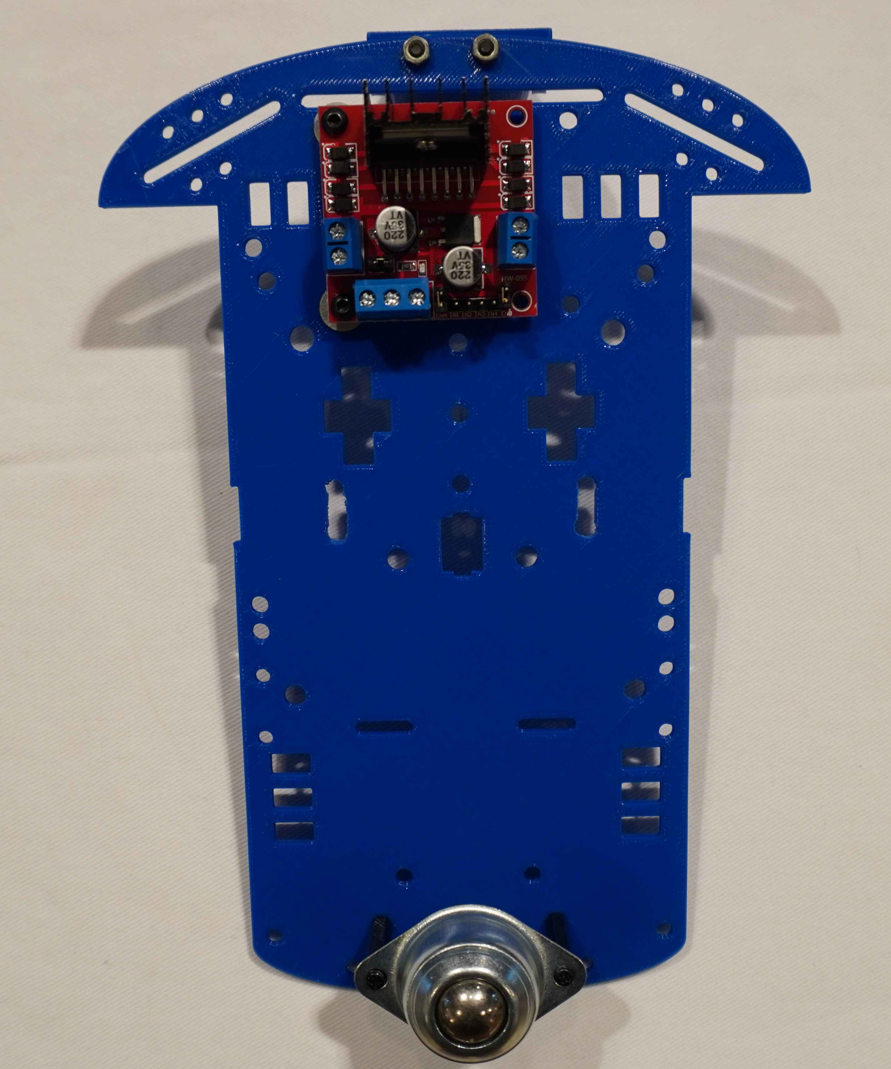
Assembly Process
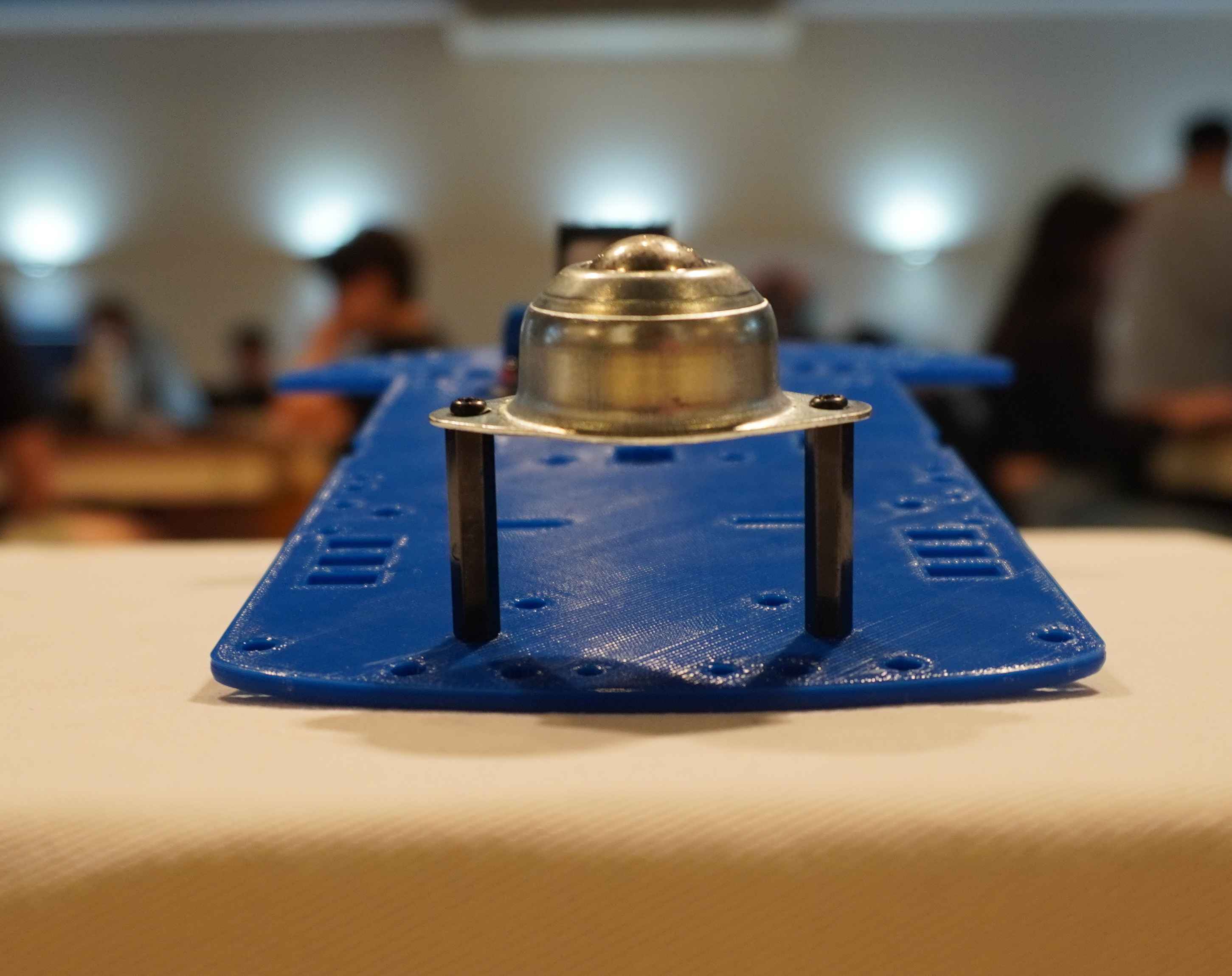
- Screw the Motor Driver and the idler wheel to the lower chassis.
Here you have a front image of how the caster wheel are mounted to the chassis:
- Screw the 3D printed parts for the Raspi Camera Module:
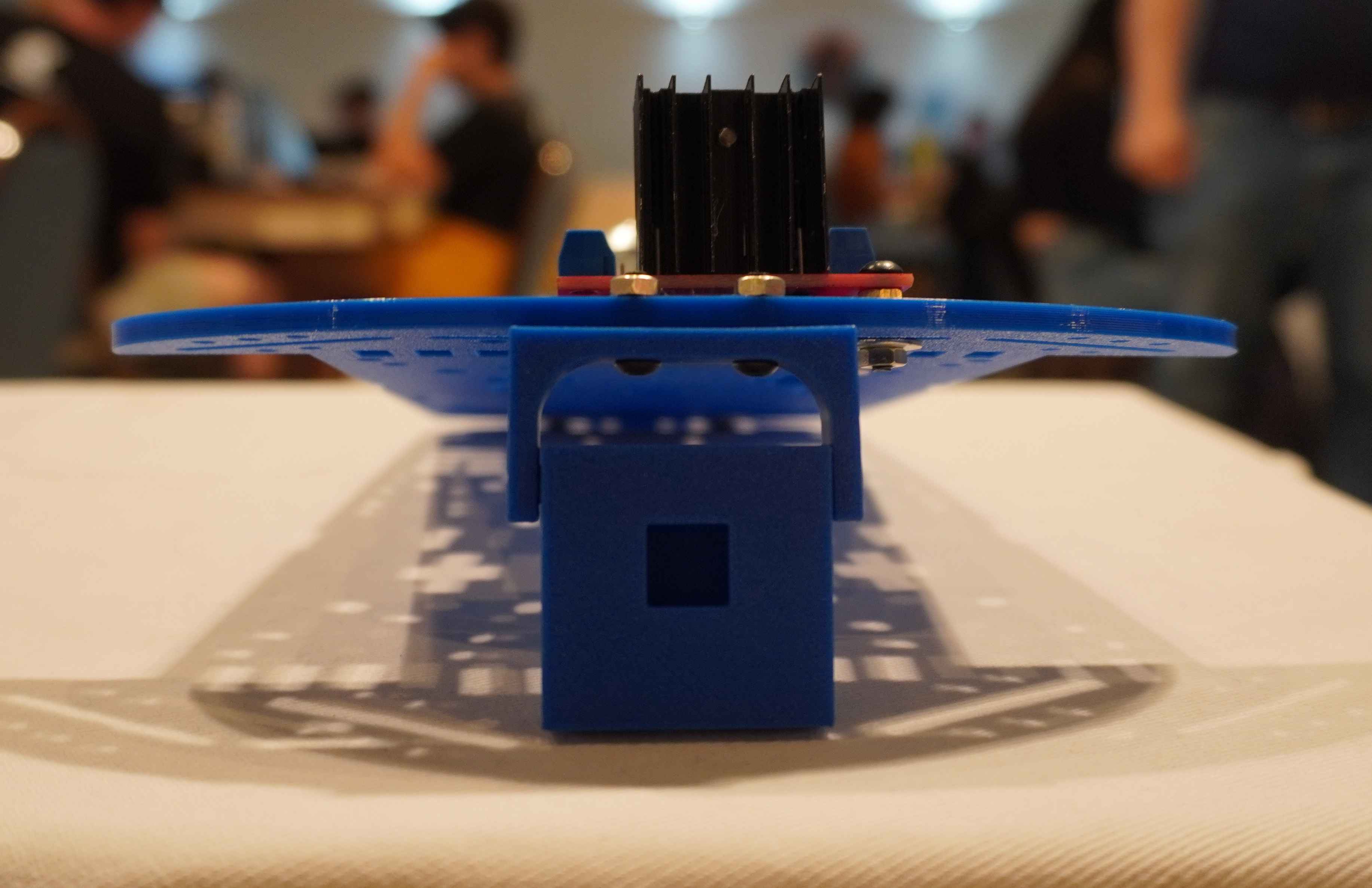
- Add the Arduino Nano to the back of the lower part of the chassis. It should look like this:
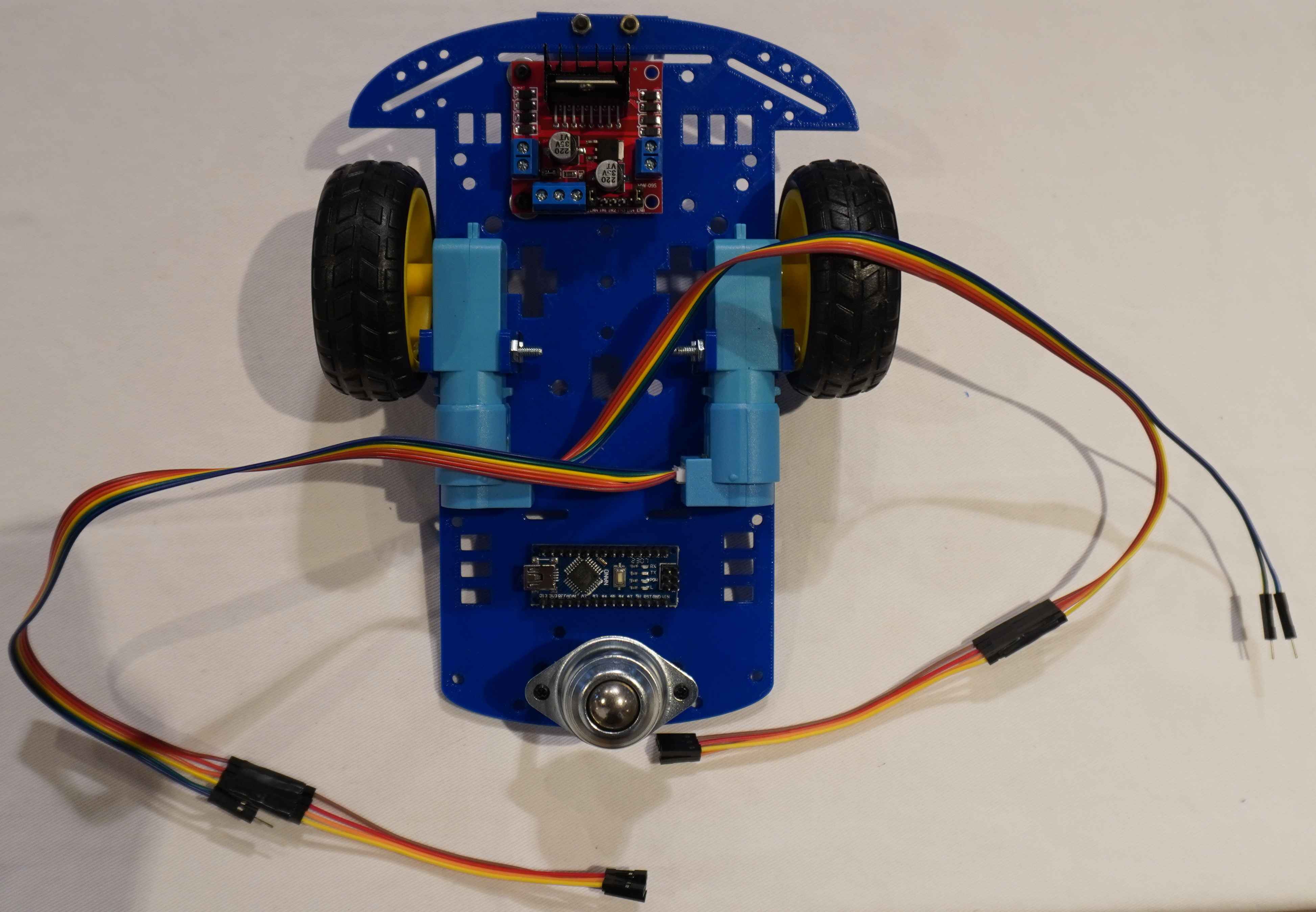
- Screw the Raspberry Pi and the DC-DC converter to the front of the lower part of the chassis:
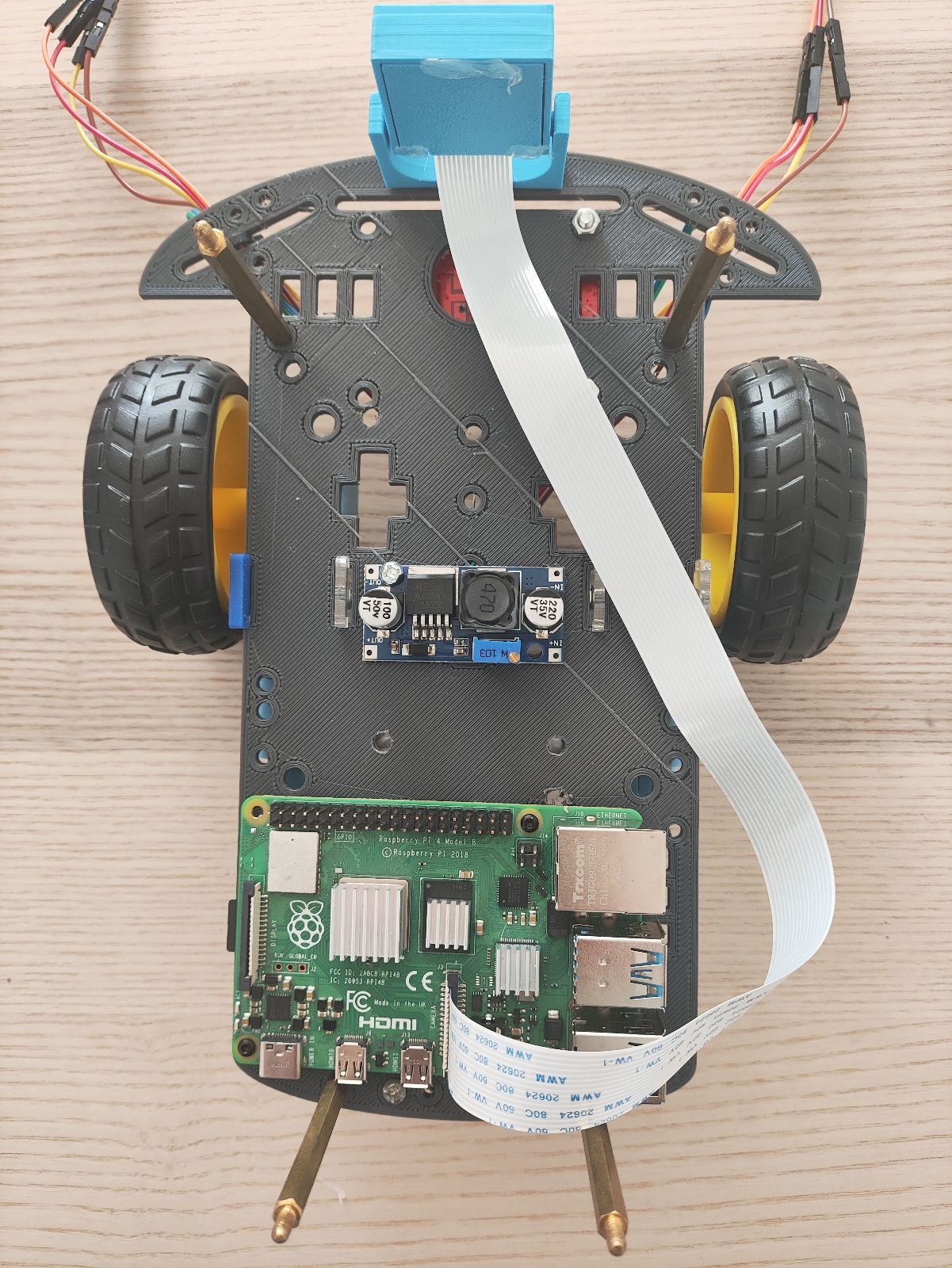
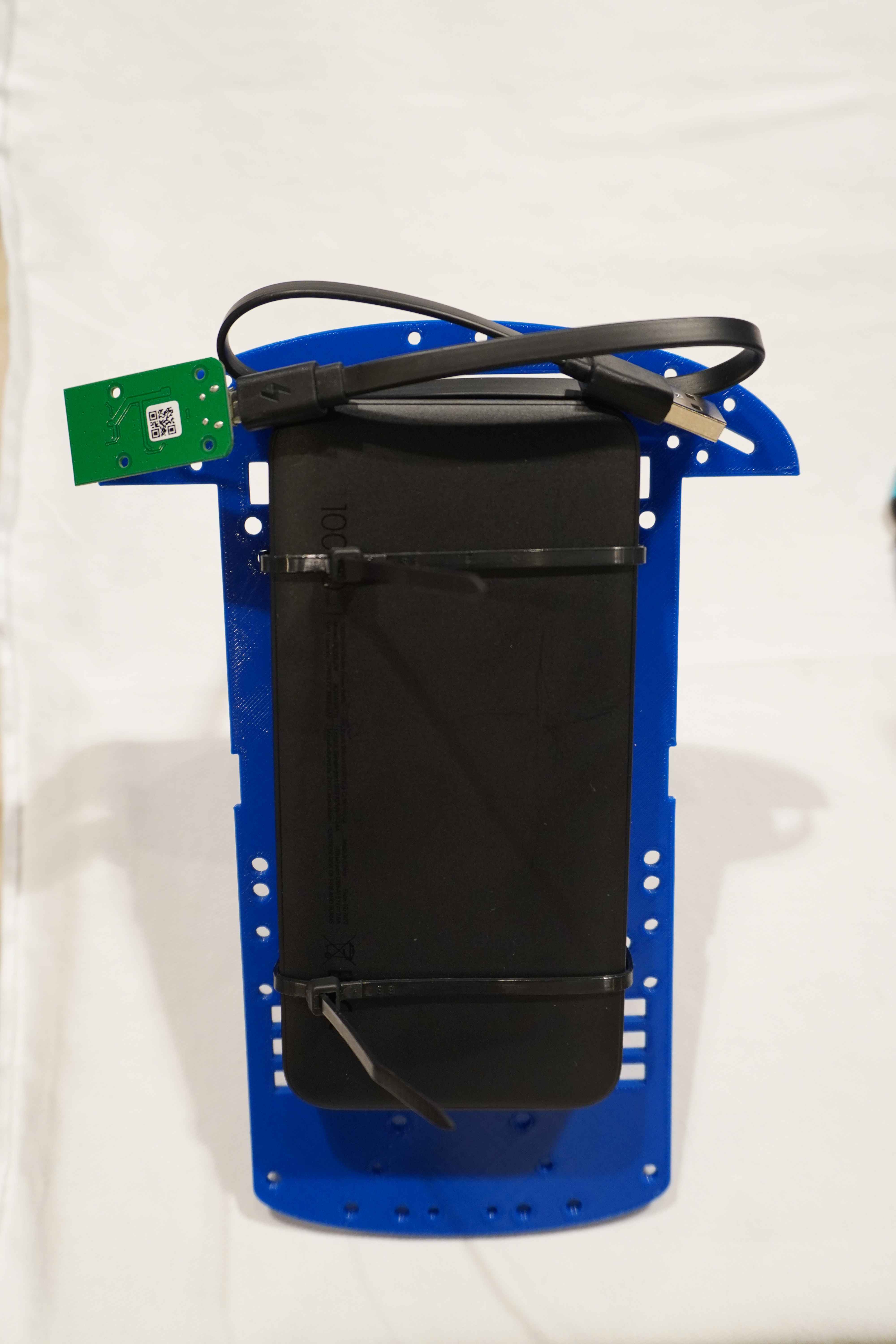
- Fix the powerbank to the back of the upper part of the chassis:
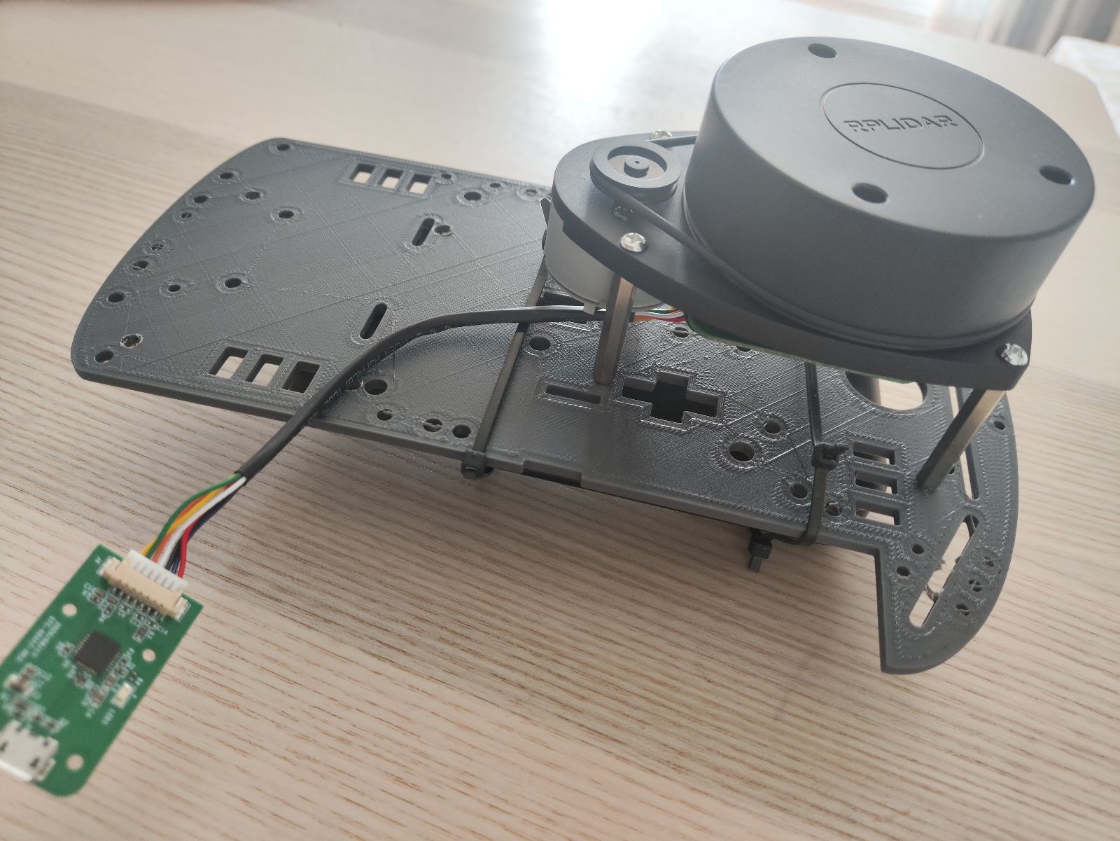
- Add the RPLidar to the front of the upper part of the chassis:
- Add the IMU (WIP)
-
Perform all the wiring following the Connections Diagram of both the upper and lower chassis. Note that some of the connections may need to be done by soldering the cables.
-
Join both chassis together, and complete the remaining wiring to have your robot ready:
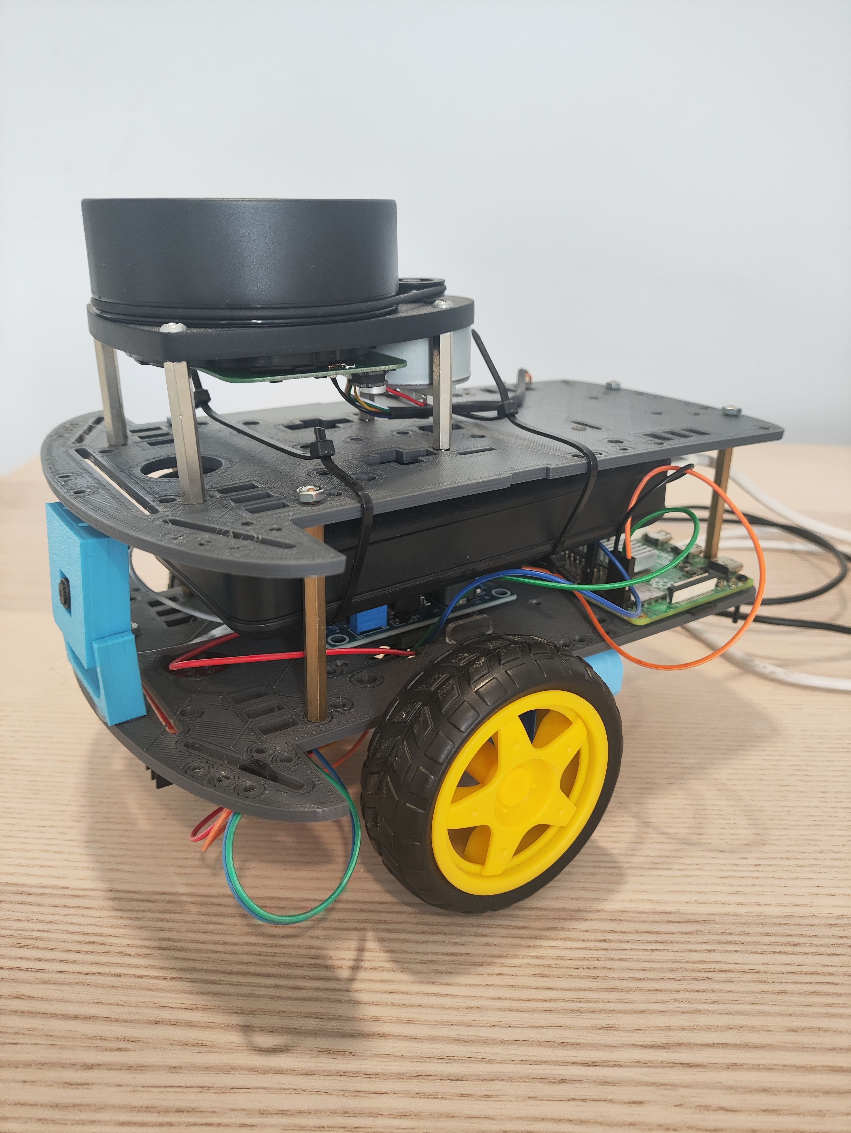
Connection Diagram
Motor-Arduino
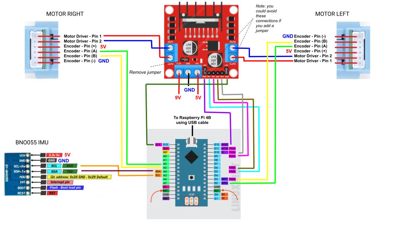
Some frequent errors:
- If one of the motors rotates in the opposite direction (think about the orientation of the motors in the chassis) probably the output(+ and -) of the L298N’s output should be toggled.
- When moving forward the encoder values should increase while moving backwards they should decrease. If it is happening the other way around probably the A and B encoder signals should be toggled.
Raspberry-Power
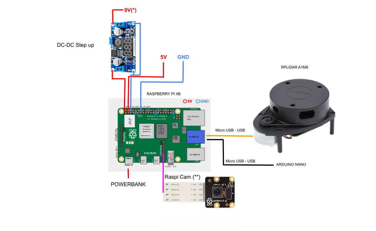
*NOTE: depending on the power bank maximum output current, the motors may need to be powered with a voltage value lower than 9V. While a higher voltage value (up to 9V) leads to smoother operation (better motor speed control), it also increases their open-loop speed, which is noticeable particularly during motion start and varies according to the power bank quality (output current capabilities). Therefore, adjusting the output voltage to lower values (around 7V) may be required so as to make the motors work as expected.
**NOTE: Ensure the ribbon cable is properly connected with the blue or silver side facing the USB ports.
Microcontroller Configuration
For uploading the microcontroller firmware please refer to andino_firmware package.
Single Board Computer (SBC)
The SBC used in this project is a Raspberry Pi 4b so the guidelines here will refer particularly to this family of on-board computers, however extending its use to other families is possible as well.
File truncated at 100 lines see the full file
Changelog for package andino_hardware
0.2.0 (2024-07-19)
- Camera info yaml (#231)
- Update andino_hardware README.md (#256)
- Update connections diagram (#252)
- Add new Arduino diagram (#249)
- Add a note about not updated diagram (#248)
- Update bill of materials (#241)
- Adds some clarifications about the installation process. (#199)
- Contributors: Agustin Alba Chicar, Franco Cipollone, Jesús Silva
0.1.0 (2023-10-09)
Dependant Packages
Launch files
Messages
Services
Plugins
Recent questions tagged andino_hardware at Robotics Stack Exchange
|
|
andino_hardware package from andino repoandino_apps andino_base andino_bringup andino_control andino_description andino_firmware andino_gz_classic andino_hardware andino_navigation andino_slam |
ROS Distro
|
Package Summary
| Version | 0.2.0 |
| License | BSD Clause 3 |
| Build type | AMENT_CMAKE |
| Use | RECOMMENDED |
Repository Summary
| Checkout URI | https://github.com/Ekumen-OS/andino.git |
| VCS Type | git |
| VCS Version | humble |
| Last Updated | 2026-02-20 |
| Dev Status | DEVELOPED |
| Released | RELEASED |
| Contributing |
Help Wanted (-)
Good First Issues (-) Pull Requests to Review (-) |
Package Description
Maintainers
- Franco Cipollone
- Javier Balloffet
Authors
andino_hardware
This package aims to provide the necessary information to the correct assembly of the robot.
Bill of Materials
| Number | Module | Part | Links | Comments |
|---|---|---|---|---|
| 1 | SBC | Raspberry Pi 4 B (4 Gb) | PiShop, TiendaTec | If you want better performance you could buy the 8GB model |
| 2 | Chassis | 2 x Print 3d Chassis + Rubber Tyre Wheels | Chassis, Wheels Sparkfun | - |
| 3 | Motors | 2 x Motor with Encoder | Sparkfun | - |
| 4 | Microcontroller | Arduino Nano | Amazon | You can also use an Arduino Uno, but mind size. It should include a microUSB - USB cable. If not, you will need to purchase it. |
| 5 | Motor Driver | L298N Dual H Bridge | Amazon | - |
| 6 | Laser Scanner | RPLidar A1M8 | RobotShop, Amazon | If no microUSB-USB cable is included, you will need to purchase one |
| 7 | Camera | Raspi Camera Module V2, 8 MP | Robotshop, Amazon, Longer cable | A link for a longer cable (30 cm) is included, just in case the one included with the camera is too short. |
| 8 | Electrical Power Supply | Powerbank 5V | Amazon | Any powerbank is suitable: Mind size / weight / output current(>=2A) |
| 9 | Power Step up | DC - DC boost converter | Amazon Europe | If motors support higher voltage than 5V a step-up(e.g: to 9V) can be added between powerbank (5V) and motor driver. Screw clockwise to reduce the output voltage. |
| 10 | Fixing & Mount | M3 bolts/fasteners - M3 Spacers - M2.5/2.0 bolts/fasteners for SBC | Mercado Libre, Amazon, Spacers | You will probably need to replace the default spacers for the LiDAR with M3 spacers |
| 11 | Other 3D printed parts | Camera Mount | 3D models | These parts are for fixing the Raspi Cam at the front of the robot |
| 12 | Caster wheel | Caster wheel | Amazon | - |
| 13 | SD Card | 64 GB SD Card | Apokin, Amazon | The SD Card is used to host the OS for the Raspberry Pi |
| 14 | (Optional) Plastic seals | - | - | You will need at least 2 longer ones to fix the powerbank to the upper chassis, and the shorter ones for all the wires. If you don’t want to use them, you can use other method to fix the powerbank and wires |
When you gather all the parts, you should have the following (NOTE: the printed encoder wheels are no longer necessary, since the motors are equipped with an embedded encoder):
Tooling
| Number | Tool | Links | Comments |
|---|---|---|---|
| 1 | Set of screwdrivers | Amazon | You need flat and star screwdrivers |
| 2 | Silicon Pistol | Amazon | This pistol should include 75 silicon bars so you won’t need to purchase them separately |
Assembly Process
- Screw the Motor Driver and the idler wheel to the lower chassis.
Here you have a front image of how the caster wheel are mounted to the chassis:
- Screw the 3D printed parts for the Raspi Camera Module:
- Add the Arduino Nano to the back of the lower part of the chassis. It should look like this:
- Screw the Raspberry Pi and the DC-DC converter to the front of the lower part of the chassis:
- Fix the powerbank to the back of the upper part of the chassis:
- Add the RPLidar to the front of the upper part of the chassis:
- Add the IMU (WIP)
-
Perform all the wiring following the Connections Diagram of both the upper and lower chassis. Note that some of the connections may need to be done by soldering the cables.
-
Join both chassis together, and complete the remaining wiring to have your robot ready:
Connection Diagram
Motor-Arduino
Some frequent errors:
- If one of the motors rotates in the opposite direction (think about the orientation of the motors in the chassis) probably the output(+ and -) of the L298N’s output should be toggled.
- When moving forward the encoder values should increase while moving backwards they should decrease. If it is happening the other way around probably the A and B encoder signals should be toggled.
Raspberry-Power
*NOTE: depending on the power bank maximum output current, the motors may need to be powered with a voltage value lower than 9V. While a higher voltage value (up to 9V) leads to smoother operation (better motor speed control), it also increases their open-loop speed, which is noticeable particularly during motion start and varies according to the power bank quality (output current capabilities). Therefore, adjusting the output voltage to lower values (around 7V) may be required so as to make the motors work as expected.
**NOTE: Ensure the ribbon cable is properly connected with the blue or silver side facing the USB ports.
Microcontroller Configuration
For uploading the microcontroller firmware please refer to andino_firmware package.
Single Board Computer (SBC)
The SBC used in this project is a Raspberry Pi 4b so the guidelines here will refer particularly to this family of on-board computers, however extending its use to other families is possible as well.
File truncated at 100 lines see the full file
Changelog for package andino_hardware
0.2.0 (2024-07-19)
- Camera info yaml (#231)
- Update andino_hardware README.md (#256)
- Update connections diagram (#252)
- Add new Arduino diagram (#249)
- Add a note about not updated diagram (#248)
- Update bill of materials (#241)
- Adds some clarifications about the installation process. (#199)
- Contributors: Agustin Alba Chicar, Franco Cipollone, Jesús Silva