Repository Summary
| Checkout URI | https://github.com/tork-a/adi_driver.git |
| VCS Type | git |
| VCS Version | master |
| Last Updated | 2022-02-04 |
| Dev Status | DEVELOPED |
| Released | RELEASED |
| Contributing |
Help Wanted (-)
Good First Issues (-) Pull Requests to Review (-) |
Packages
| Name | Version |
|---|---|
| adi_driver | 1.0.3 |
README
adi_driver 

This package contains ROS driver nodes for Analog Devices(ADI) sensor products mainly communicate by SPI(Serial Periferal Interface).
Currently supported devices are:
-
ADIS16470
- Wide Dynamic Range Mini MEMS IMU
-
ADXL345:
- 3-Axis, ±2 g/±4 g/±8 g/±16 g Digital Accelerometer
- The support for this device is experimental
-
ADIS16495
- Higher grade MEMS IMU
- The support for this device is experimental
You need a SPI interface on your PC to communicate with device. This package supports Devantech’s USB-IIS as the USB-SPI converter.
USB-IIS
Overview
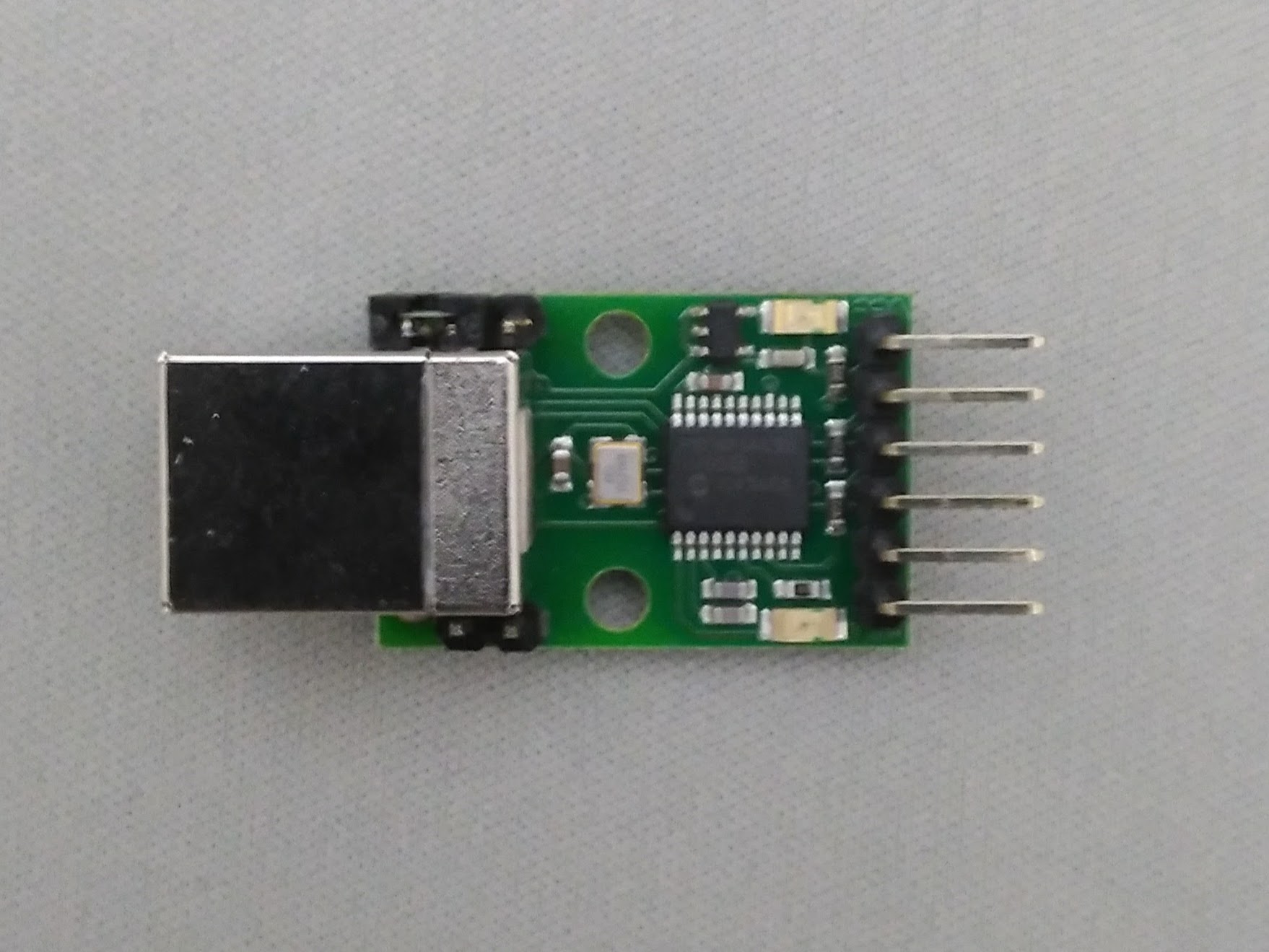
USB-IIS is a USB to Serial/I2C/SPI converter, simple, small and easy to use. You don’t need any extra library like libusb or libftdi. The device is available on /dev/ttyACM* as modem device.
Please consult the product information and SPI documentation for the detail.
Tips
You need to remove the jumper block on Power link pins to provide
3.3V for the device.
You need to add your user to dialout group to acces /dev/ttyACM* .
``` $ sudo adduser your_user_name dialout
If it takes several seconds until /dev/ttyACM* available, you need to
uninstall modemmanager as:


``` $ sudo apt remove modemmanager
ADIS16470
Overview
ADIS16470 is a complete inertial system that includes a triaxis gyroscope and a triaxis accelerometer.
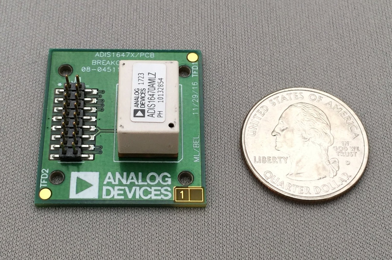
You can use Breakout board for easy use.
Connection
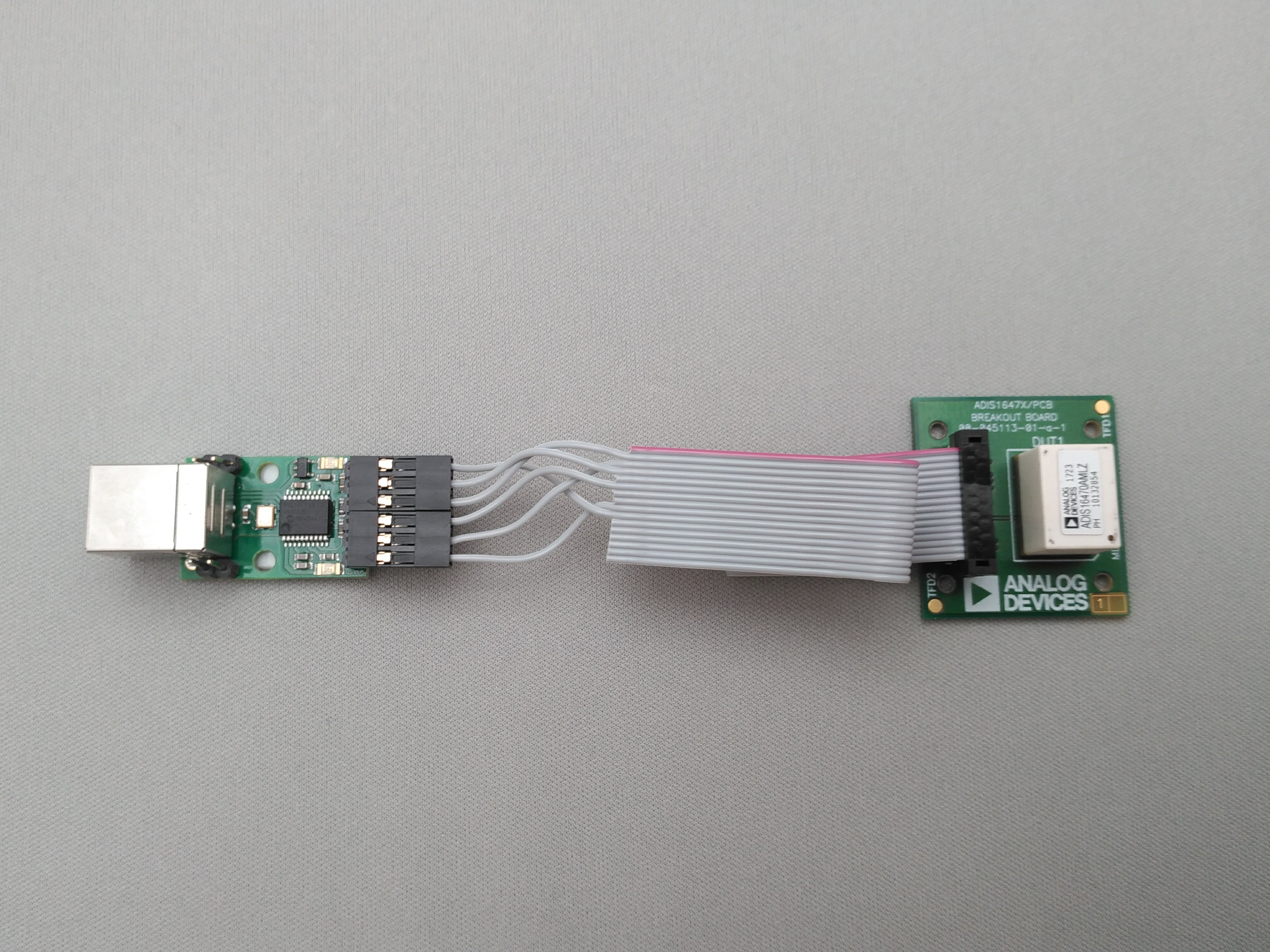
You need to build a flat cable to connect the USB-ISS and the ADIS16470 breakout board. The picture shows a implementation.
Very simple schematic is here. J1 is the USB-ISS pin and J2 is the 2mm pin headers on the ADIS16470 breakout board.
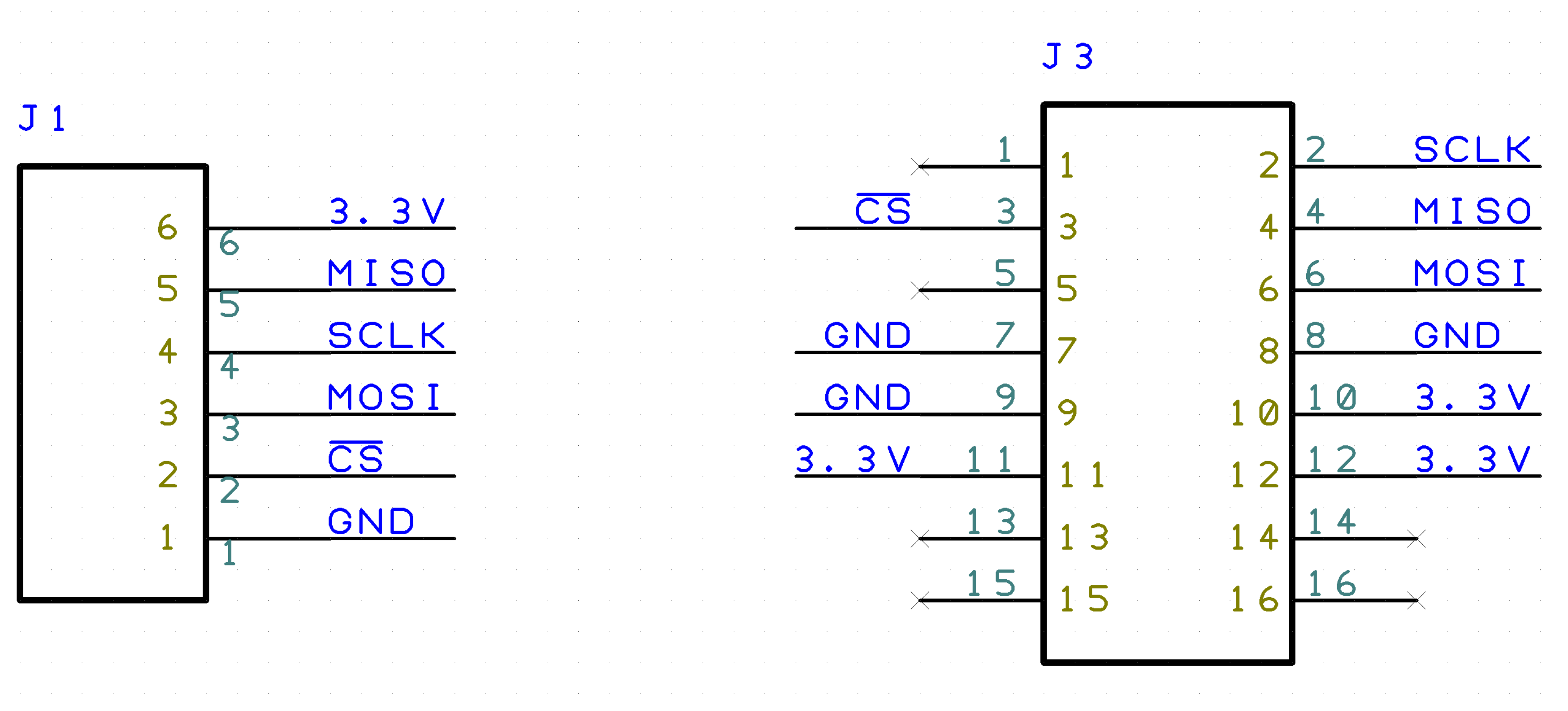
Note: you only need to connect one of the power-line(3.3V and GND). They are connected in the breakout board.
BOM
- J1: 2550 Connector 6pin
- Available at Akiduki
- J2: FCI Connector for 1.0mm pitch ribon cables
- Available at RS Components
- 1.0 mm pitch ribon cable
- Available at Aitendo
Quick start
File truncated at 100 lines see the full file
CONTRIBUTING
Repository Summary
| Checkout URI | https://github.com/tork-a/adi_driver.git |
| VCS Type | git |
| VCS Version | master |
| Last Updated | 2022-02-04 |
| Dev Status | DEVELOPED |
| Released | RELEASED |
| Contributing |
Help Wanted (-)
Good First Issues (-) Pull Requests to Review (-) |
Packages
| Name | Version |
|---|---|
| adi_driver | 1.0.3 |
README
adi_driver
This package contains ROS driver nodes for Analog Devices(ADI) sensor products mainly communicate by SPI(Serial Periferal Interface).
Currently supported devices are:
-
ADIS16470
- Wide Dynamic Range Mini MEMS IMU
-
ADXL345:
- 3-Axis, ±2 g/±4 g/±8 g/±16 g Digital Accelerometer
- The support for this device is experimental
-
ADIS16495
- Higher grade MEMS IMU
- The support for this device is experimental
You need a SPI interface on your PC to communicate with device. This package supports Devantech’s USB-IIS as the USB-SPI converter.
USB-IIS
Overview
USB-IIS is a USB to Serial/I2C/SPI converter, simple, small and easy to use. You don’t need any extra library like libusb or libftdi. The device is available on /dev/ttyACM* as modem device.
Please consult the product information and SPI documentation for the detail.
Tips
You need to remove the jumper block on Power link pins to provide
3.3V for the device.
You need to add your user to dialout group to acces /dev/ttyACM* .
``` $ sudo adduser your_user_name dialout
If it takes several seconds until /dev/ttyACM* available, you need to
uninstall modemmanager as:


``` $ sudo apt remove modemmanager
ADIS16470
Overview
ADIS16470 is a complete inertial system that includes a triaxis gyroscope and a triaxis accelerometer.
You can use Breakout board for easy use.
Connection
You need to build a flat cable to connect the USB-ISS and the ADIS16470 breakout board. The picture shows a implementation.
Very simple schematic is here. J1 is the USB-ISS pin and J2 is the 2mm pin headers on the ADIS16470 breakout board.
Note: you only need to connect one of the power-line(3.3V and GND). They are connected in the breakout board.
BOM
- J1: 2550 Connector 6pin
- Available at Akiduki
- J2: FCI Connector for 1.0mm pitch ribon cables
- Available at RS Components
- 1.0 mm pitch ribon cable
- Available at Aitendo
Quick start
File truncated at 100 lines see the full file